CarPort Docs
Software Documentation
CarPort Documentation
💡 The content of this document refers to CarPort Version 3.1. Older or newer versions may have different features.
Introduction
CarPort is a specialized diagnostic software for Microsoft Windows, developed for the maintenance, repair, and configuration of Volkswagen Group vehicles. The software supports almost all vehicles of the VW, Audi, SEAT, Škoda, and Cupra brands from model year 1990 onwards and is aimed at both ambitious private users and professional workshops looking for a cost-effective alternative to OEM diagnostic systems.
Unlike generic OBD-2 scanners, which only provide access to emissions-related parameters of the engine control unit, CarPort implements the manufacturer-specific diagnostic protocols KWP1281, KWP2000, and UDS. This gives you full access to all control units installed in the vehicle – from engine management, airbag, and braking systems to comfort electronics and infotainment. Depending on the vehicle generation, communication takes place via the K-line (older vehicles up to approx. 2004) or the CAN bus (modern vehicles). CarPort automatically detects the respective configuration and abstracts the technical details, allowing you to concentrate on the actual diagnostic work.
The range of functions covers all essential areas of vehicle diagnostics: reading and clearing fault codes, real-time monitoring of sensor and actuator data, targeted activation of actuators, coding and adaptation of control unit functions, as well as performing basic settings after repairs. Furthermore, CarPort addresses the specific challenges of VAG diagnostics – such as the coexistence of different protocol generations in one vehicle, protected access areas with login codes, and the cryptographic protection mechanisms (SFD) used in the latest vehicle generations. The individual functions are described in detail in the following chapters.
Prerequisites & Compatibility
To use CarPort without restrictions, both your computer system and the diagnostic interface used must meet certain requirements.
System Requirements
CarPort is designed as a native Windows application. For smooth operation, we recommend the following system configuration:
- Operating System: Windows 10 or Windows 11 (64-bit version each).
- Processor & Memory: A standard laptop or tablet with x86-64 architecture (min. dual-core, 4 GB RAM).
- Hard Drive Space: Approx. 2 GB of free storage space for program files and logs.
- Interfaces: USB-A or USB-C port for the diagnostic interface.
- Internet Connection: Mandatory for the initial activation and updates. The actual vehicle diagnostics work completely offline.
Note on "Windows on Arm": This architecture is not officially supported. Thanks to the x64 emulation integrated into Windows, operation is often still possible, but it strictly requires special ARM64 drivers for the interface (see Installation).
Supported Vehicles
CarPort supports almost all vehicles of the brands Volkswagen, Audi, SEAT, Škoda, Cupra from the year of manufacture 1990 to today.
The following table provides information on the compatibility of specific models. To identify your vehicle, please compare the type code.
| Manufacturer | Model | Type Code | Production Period | Notes |
|---|---|---|---|---|
| Audi | 80 | 8C | 1992 - 1995 | 2x2 adapter required |
| Audi | 100 | 4A | 1991 - 1994 | |
| Audi | A1 | 8X | 2010 - 2018 | |
| Audi | A1 | GB | 2018 - 2025 | SFD/UNECE from 2024 |
| Audi | A2 | 8Z | 1999 - 2005 | |
| Audi | A3 | 8L | 1996 - 2003 | |
| Audi | A3 | 8P | 2003 - 2013 | |
| Audi | A3 | 8V | 2012 - 2020 | |
| Audi | A3 | 8Y | 2020 - 2025 | SFD from 2020; SFD/UNECE from 2024 |
| Audi | A4 B5 | 8D | 1994 - 2001 | |
| Audi | A4 B6 | 8E | 2000 - 2004 | |
| Audi | A4 B7 | 8E | 2004 - 2008 | |
| Audi | A4 B8 | 8K | 2007 - 2015 | |
| Audi | A4 B9 | 8W | 2015 - 2024 | SFD/UNECE from 2024 |
| Audi | A4 Cabriolet | 8H | 2002 - 2009 | |
| Audi | A5 | 8T | 2007 - 2016 | |
| Audi | A5 | 8F | 2009 - 2016 | |
| Audi | A5 | F5 | 2016 - 2024 | SFD/UNECE from 2024 |
| Audi | A5 B10 | FU | 2024 - 2025 | SFD/UNECE from 2024 |
| Audi | A6 C4 | 4A | 1994 - 1997 | |
| Audi | A6 C5 | 4B | 1997 - 2005 | |
| Audi | A6 C6 | 4F | 2004 - 2011 | |
| Audi | A6 C7 | 4G | 2011 - 2018 | |
| Audi | A6 C8 | 4A/F2 | 2018 - 2025 | SFD/UNECE from 2024 |
| Audi | A6 C9 | - | 2025 - | SFD/UNECE |
| Audi | A7 C7 | 4G | 2010 - 2018 | |
| Audi | A7 C8 | 4K/F2 | 2018 - 2025 | SFD/UNECE from 2024 |
| Audi | A8 D2 | 4D | 1994 - 2002 | |
| Audi | A8 D3 | 4E | 2002 - 2010 | |
| Audi | A8 D4 | 4H | 2010 - 2017 | |
| Audi | A8 D5 | 4N/F8 | 2017 - 2025 | SFD/UNECE from 2024 |
| Audi | Cabrio | 8G | 1991 - 2000 | 2x2 adapter required |
| Audi | e-tron GT | FW | 2021 - 2025 | SFD from 2021; SFD/UNECE from 2024 |
| Audi | Q2 | GA | 2016 - 2025 | SFD/UNECE from 2024 |
| Audi | Q3 | 8U | 2011 - 2018 | |
| Audi | Q3 | F3 | 2018 - 2025 | SFD/UNECE from 2024 |
| Audi | Q4 e-tron | FZ | 2021 - 2025 | SFD from 2021; SFD/UNECE from 2024 |
| Audi | Q5 | 8R | 2008 - 2017 | |
| Audi | Q5 | FY | 2017 - 2025 | SFD/UNECE from 2024 |
| Audi | Q6 e-tron | GF | 2024 - 2025 | SFD/UNECE from 2024 |
| Audi | Q7 | 4L | 2006 - 2015 | |
| Audi | Q7 | 4M | 2015 - 2025 | SFD/UNECE from 2023 |
| Audi | Q8 | 4M | 2018 - 2025 | SFD/UNECE from 2023 |
| Audi | Q8 e-tron | GE | 2018 - 2025 | SFD/UNECE from 2024 |
| Audi | R8 | 42 | 2006 - 2015 | |
| Audi | R8 | 4S/FX | 2015 - 2024 | |
| Audi | TT | 8N | 1998 - 2006 | |
| Audi | TT | 8J | 2006 - 2014 | |
| Audi | TT | FV | 2014 - 2023 | |
| Cupra | Born | K1 | 2021 - 2025 | SFD from 2022; SFD/UNECE from 2024 |
| Cupra | Formentor | KM7 | 2020 - 2025 | SFD from 2020; SFD/UNECE from 2024 |
| Cupra | Tavascan | VZ | 2023 - 2025 | SFD from 2023; SFD/UNECE from 2024 |
| Ford | Explorer | - | 2020 - 2025 | SFD/UNECE from 2024; identical to ID.4 |
| Ford | Galaxy | WG | 1996 - 2006 | identical to VW Sharan 7M |
| Ford | Tourneo Connect | - | 2022 - 2025 | SFD from 2022; identical to VW Caddy V |
| MAN | TGE | SY | 2017 - 2025 | SFD/UNECE from 2024; identical to VW Crafter 2 |
| Seat | Alhambra 1 | 7V | 1996 - 2010 | |
| Seat | Alhambra 2 | 71 | 2011 - 2020 | |
| Seat | Altea | 5P | 2004 - 2015 | |
| Seat | Arona | KJ7 | 2017 - 2025 | SFD/UNECE from 2024 |
| Seat | Arosa | 6H | 1997 - 2004 | |
| Seat | Ateca | 5FP/KH7 | 2016 - 2025 | SFD/UNECE from 2024 |
| Seat | Exeo | 3R | 2008 - 2013 | |
| Seat | Ibiza 2 | 6K | 1993 - 2002 | |
| Seat | Ibiza 3 | 6L | 2002 - 2008 | |
| Seat | Ibiza 4 | 6J/6P | 2009 - 2017 | |
| Seat | Ibiza 5 | 6F | 2017 - 2025 | SFD/UNECE from 2024 |
| Seat | Inca | 9KS | 1995 - 2003 | |
| Seat | Leon 1 | 1M | 1999 - 2006 | |
| Seat | Leon 2 | 1P | 2005 - 2012 | |
| Seat | Leon 3 | 5F | 2012 - 2020 | |
| Seat | Leon 4 | KL | 2020 - 2025 | SFD from 2020; SFD/UNECE from 2024 |
| Seat | Mii | KF | 2011 - 2021 | |
| Seat | Tarraco | KN | 2018 - 2024 | SFD/UNECE from 2024 |
| Seat | Toledo 1 | 1L | 1991 - 1999 | 2x2 adapter required |
| Seat | Toledo 2 | 1M | 1999 - 2004 | |
| Seat | Toledo 3 | 5P | 2004 - 2009 | |
| Seat | Toledo 4 | KG | 2012 - 2019 | |
| Škoda | Citigo | NF | 2012 - 2020 | |
| Škoda | Enyaq iV | NY/5A | 2020 - 2025 | SFD from 2020; SFD/UNECE from 2024 |
| Škoda | Fabia 1 | 6Y | 1999 - 2007 | |
| Škoda | Fabia 2 | 5J | 2007 - 2014 | |
| Škoda | Fabia 3 | NJ | 2014 - 2021 | |
| Škoda | Fabia 4 | PJ | 2021 - 2025 | SFD/UNECE from 2024 |
| Škoda | Felicia | 6U | 1995 - 2001 | |
| Škoda | Kamiq | NW | 2020 - 2025 | SFD/UNECE from 2024 |
| Škoda | Karoq | NS/NU | 2017 - 2025 | SFD/UNECE from 2024 |
| Škoda | Kodiaq 1 | NS | 2017 - 2023 | |
| Škoda | Kodiaq 2 | PS | 2019 - 2025 | SFD/UNECE from 2024 |
| Škoda | Octavia 1 | 1U | 1996 - 2010 | |
| Škoda | Octavia 2 | 1Z | 2004 - 2013 | |
| Škoda | Octavia 3 | 5E | 2013 - 2020 | |
| Škoda | Octavia 4 | NN/NX | 2020 - 2025 | SFD from 2020; SFD/UNECE from 2024 |
| Škoda | Pick Up | 67 | 1995 - 2001 | |
| Škoda | Rapid | NH | 2012 - 2019 | |
| Škoda | Roomster | 5J | 2006 - 2015 | |
| Škoda | Scala | NW1 | 2019 - 2025 | SFD/UNECE from 2024 |
| Škoda | Superb 1 | 3U | 2001 - 2008 | |
| Škoda | Superb 2 | 3T | 2008 - 2015 | |
| Škoda | Superb 3 | 3V | 2015 - 2023 | |
| Škoda | Superb 4 | 3Y | 2023 - 2025 | SFD from 2023; SFD/UNECE from 2024 |
| Škoda | Yeti | 5L | 2009 - 2017 | |
| VW | Amarok | 2H | 2010 - 2023 | |
| VW | Arteon | 3H | 2017 - 2024 | SFD/UNECE from 2024 |
| VW | Beetle | 5C | 2011 - 2019 | |
| VW | Bora | 1J | 1998 - 2005 | |
| VW | Caddy 2 | 9KV | 1995 - 2003 | |
| VW | Caddy 3 | 2K | 2003 - 2015 | |
| VW | Caddy 4 | SA | 2015 - 2020 | |
| VW | Caddy 5 | SB | 2020 - 2025 | SFD from 2021 |
| VW | CC | 35 | 2008 - 2016 | |
| VW | Corrado | 50 | 1991 - 1995 | 2x2 adapter required |
| VW | Crafter 2 | SY/SZ | 2017 - 2025 | SFD from 2023; SFD/UNECE from 2024 |
| VW | Eos | 1F | 2006 - 2015 | |
| VW | Fox | 5Z | 2005 - 2011 | |
| VW | Gol 2 | AB9 | 1994 - 2013 | |
| VW | Gol 3 | NF | 2008 - 2022 | |
| VW | Golf 2 | 1G | 1991 - 1992 | 2x2 adapter required |
| VW | Golf 3 | 1H | 1991 - 1997 | 2x2 adapter required |
| VW | Golf 4 | 1J | 1997 - 2006 | |
| VW | Golf 5 | 1K | 2003 - 2008 | |
| VW | Golf 6 | 5K | 2008 - 2012 | |
| VW | Golf 7 | AU | 2012 - 2020 | |
| VW | Golf 8 | CD | 2020 - 2025 | SFD from 2020; SFD/UNECE from 2024 |
| VW | Golf Plus | 5M | 2004 - 2014 | |
| VW | Golf Sportsvan | AM | 2014 - 2020 | |
| VW | ID Buzz | EB | 2022 - 2025 | SFD from 2022; SFD/UNECE from 2024 |
| VW | ID.3 | E11 | 2019 - 2025 | SFD from 2020; SFD/UNECE from 2024 |
| VW | ID.4 | E21 | 2020 - 2025 | SFD from 2021; SFD/UNECE from 2024 |
| VW | ID.5 | E39 | 2022 - 2025 | SFD from 2022; SFD/UNECE from 2024 |
| VW | ID.7 | ED | 2023 - 2025 | SFD/UNECE from 2024 |
| VW | Jetta 5 | 1K | 2005 - 2010 | |
| VW | Jetta 6 | 162 | 2010 - 2018 | |
| VW | Lupo | 6E/6X | 1998 - 2005 | |
| VW | Mexico Käfer | 11 | 1991 - 2002 | |
| VW | Multivan (T7) | ST | 2022 - 2025 | SFD from 2022; SFD/UNECE from 2024 |
| VW | New Beetle | 9C | 1997 - 2010 | |
| VW | New Beetle Cabriolet | 1Y | 2003 - 2010 | |
| VW | Passat B3 | 31 | 1991 - 1993 | 2x2 adapter required |
| VW | Passat B4 | 3A | 1993 - 1997 | |
| VW | Passat B5 | 3B | 1996 - 2005 | |
| VW | Passat B6 | 3C | 2005 - 2010 | |
| VW | Passat B7 | 3C | 2010 - 2015 | |
| VW | Passat B8 | 3G | 2014 - 2023 | |
| VW | Passat B9 | CJ | 2023 - 2025 | SFD from 2023; SFD/UNECE from 2024 |
| VW | Phaeton | 3D | 2002 - 2016 | |
| VW | Polo 2 | 86C | 1991 - 1994 | 2x2 adapter required |
| VW | Polo 3 | 6N | 1994 - 2001 | |
| VW | Polo 4 | 9N | 2001 - 2009 | |
| VW | Polo 5 | 6R | 2009 - 2017 | |
| VW | Polo 5 | 6C | 2014 - 2017 | |
| VW | Polo 6 | AW | 2017 - 2025 | SFD/UNECE from 2024 |
| VW | Scirocco | 13 | 2009 - 2017 | |
| VW | Sharan 1 | 7M | 1996 - 2010 | |
| VW | Sharan 2 | 7N | 2010 - 2022 | |
| VW | T-Cross | C1 | 2019 - 2025 | SFD/UNECE from 2024 |
| VW | T-Cross | D31 | 2019 - 2025 | SFD/UNECE from 2024 |
| VW | T-Roc | A1 | 2017 - 2025 | SFD/UNECE from 2024 |
| VW | T-Roc | AC8 | 2020 - 2025 | SFD/UNECE from 2024 |
| VW | T4 | 70 | 1991 - 1995 | 2x2 adapter required |
| VW | T4 | 7D | 1996 - 2003 | |
| VW | T5 | 7H/7E | 2003 - 2015 | |
| VW | T6 | SG | 2015 - 2019 | |
| VW | T6.1 | SH | 2019 - 2023 | |
| VW | Taigo | CS | 2021 - 2025 | SFD/UNECE from 2024 |
| VW | Tayron | R41 | 2024 - 2025 | SFD/UNECE |
| VW | Tiguan 1 | 5N | 2007 - 2017 | |
| VW | Tiguan 2 | AD1 | 2016 - 2024 | |
| VW | Tiguan 3 | CT | 2024 - 2025 | SFD/UNECE from 2024 |
| VW | Touareg 1 | 7L | 2002 - 2010 | |
| VW | Touareg 2 | 7P | 2010 - 2018 | |
| VW | Touareg 3 | CR7 | 2018 - 2025 | SFD/UNECE from 2024 |
| VW | Touran | 1T | 2003 - 2015 | |
| VW | Touran | 5T | 2015 - 2025 | SFD/UNECE from 2024 |
| VW | up! | 1S | 2011 - 2023 | |
| VW | Vento | 1H | 1992 - 1998 | 2x2 adapter required |
| VW | Virtus | - | 2018 - 2025 |
Write Protection and Access Restrictions (SFD, SFD2/UNECE, Secure Gateway)
In the vehicle table above, the notes SFD and SFD/UNECE can be found for newer models. These indicate different levels of access restrictions introduced by the Volkswagen Group to protect vehicle electronics. For diagnostic work with CarPort, it is important to know the differences, as they directly affect the available range of functions.
SFD (Vehicle Diagnostic Protection) – from approx. 2020:
SFD is a cryptographic protection mechanism at the control unit level that has been in use since approx. model year 2020 (Golf 8, Octavia 4, Seat Leon 4, among others). It replaces the previous Security Access (static 5-digit code) with a challenge-response procedure using a vehicle-specific token and key.
- Restriction: Write functions (Coding, Adaptation, Basic Settings) are locked until unlocked.
- Read functions (reading fault memory, measured values, control unit info) remain fully available.
- Unlocking: Possible via the offline procedure integrated into CarPort (generate token → obtain key via external service → enter key). You can find the complete instructions under SFD.
SFD/UNECE and Secure Gateway – from approx. 2024:
From model year 2024, the Volkswagen Group is implementing a so-called Secure Gateway in addition to SFD, in conjunction with the UNECE Regulation R155 (UN regulation on vehicle cybersecurity). This combination is marked as SFD/UNECE in the vehicle table.
The Secure Gateway is an access lock at the gateway level that restricts the communication path between the diagnostic interface and the control unit – even before the control unit's own SFD protection takes effect. It is therefore a two-stage protection:
| Stage | Mechanism | Level | Effect |
|---|---|---|---|
| 1. Secure Gateway | Gateway filters diagnostic commands | Vehicle Gateway (Addr. 19) | Only authorized commands are forwarded to control units |
| 2. SFD | Cryptographic authentication | Individual control unit | Write functions only after token/key unlocking |
Effects on diagnostics with CarPort:
Without additional authentication against the Secure Gateway, the following functions are available for SFD/UNECE vehicles:
- Read fault memory
- Clear fault memory
- Read control unit info
- Read measured values
The following functions are not available as long as no gateway authentication has taken place:
- Coding
- Adaptation
- Basic settings
- Output test
- Change installation list
⚠️ Important: Unlocking the Secure Gateway requires authentication at the gateway level, which goes beyond the previous SFD mechanism. This is a manufacturer-side restriction that affects all independent diagnostic systems equally. CarPort supports SFD unlocking at the control unit level (see SFD), but gateway authentication depends on the availability of compatible unlocking services.
Summary of protection levels:
| Vehicle Generation | Protection | Read Functions | Clear Fault Memory | Write Functions |
|---|---|---|---|---|
| Before 2020 | Security Access / Login | Unrestricted | Unrestricted | After entering the access code |
| From approx. 2020 (SFD) | SFD | Unrestricted | Unrestricted | After SFD unlocking (token/key) |
| From approx. 2024 (SFD/UNECE) | Secure Gateway + SFD | Unrestricted | Unrestricted | After gateway authentication + SFD unlocking |
Supported Diagnostic Hardware
The choice of the right interface largely determines which functions are available to you in CarPort. We basically distinguish between two categories:
- For VAG Vehicles (Required): To perform a complete
diagnosis on your VW, Audi, SEAT, or Škoda, you strictly need an
interface from this category. Only these special adapters allow access
to all installed control units (e.g., airbag, brakes,
climate control, comfort system, infotainment). This is the basic
prerequisite for all diagnostic functions – from simply reading fault
codes to professional adaptations. Our hardware recommendation:
- AutoDia K509
- K+CAN Commander 1.4
- CP compact
- Generic OBD-2 Diagnostics: Standard interfaces like the widely used ELM327 are exclusively suitable for emissions-related OBD-2 diagnostics of the engine control unit. Access to other VAG-specific control units (e.g., ABS, central electrics, infotainment) is technically not possible with these adapters.
The following table shows in detail which adapter enables which protocols and thus which types of diagnostics. Please note that CAN bus support is strictly required for modern vehicles (from approx. 2005).
| Designation | K-Line | CAN Bus | OBD-2 |
|---|---|---|---|
| AutoDia K509 | ✔️ | ✔️ | ✔️ |
| K+CAN Commander 1.4 | ✔️ | ✔️ | ✔️ |
| CP compact | ✔️ | ✔️ | ✔️ |
| Menke Diag 1000 | ✔️ | ✔️ | ✔️ |
| AGV 4000 expert | ✔️ | ✔️ | ✔️ |
| KKL Interface (e.g., AutoDia K409) | ✔️ | ✔️ | |
| ELM 327 (e.g., AutoDia E327) | ✔️ | ||
| DIAMEX DX35 | ✔️ | ||
| ElmScan 5 | ✔️ | ||
| mOByDic | ✔️ | ||
| OBDLink | ✔️ | ||
| Lawicel | ✔️ | ||
| TinyCAN | ✔️ | ||
| DIAMEX DXM1 | ✔️ | ✔️ | ✔️ |
Installation & Activation
Installation
To install CarPort, please proceed as follows:
- Download: Download the latest installer from our official website.
- Execution: Start the downloaded file (e.g.,
CarPort_X.X.X_Setup.exe). You may need to authorize the execution by confirming the Windows User Account Control (UAC) prompt. - Setup Wizard: Follow the on-screen instructions.
During the installation, you can configure the following settings:
- Language Selection: The installation language is automatically detected based on your system, but can be adjusted manually. This selection also determines the subsequent language of the user interface.
- Destination Directory: The default path is
C:\Program Files\CarPort. You can choose an alternative directory. - Shortcuts: Choose whether Start menu entries and desktop icons should be created.
- Driver Installation: The installer automatically sets up the necessary drivers for all supported diagnostic interfaces. Manual intervention is generally not required here.
💡 Tip: To run different CarPort versions in parallel, you can simply install them in different folders.
Special Note for Windows on Arm: On devices with ARM architecture (e.g., Surface Pro X), the device drivers for the diagnostic interface must be installed manually, as they are not included in the standard installer. You can find the appropriate ARM64 drivers on the FTDI manufacturer's website: FTDI VCP Drivers.
Activation
To use the full range of functions of your purchased license, the
software must be activated. The Activation Wizard
starts automatically the first time you open the program. You can also
access it later at any time via the Program →
Activate CarPort... menu.
Online Activation Process:
- In the wizard, select the option
Activate CarPort with activation code online (default). (Note: The optionActivate CarPort with license fileis a fallback for support cases and is not required during normal operation.) - Enter your activation code into the input field.
- Click on
Activate.- Important: For licenses tied to specific hardware, the corresponding interface must be connected to the computer during activation.
- After successful verification, the license is stored encrypted on your system. CarPort is now ready for use.
Activation Troubleshooting:
If the activation fails, the error message usually provides a direct indication of the cause:
A network error has occurred!
Connection issues. Check your internet connection. Firewalls
(especially in corporate networks) or antivirus programs often block
access to our activation server. Try temporarily allowing the
software.
The activation code is invalid!
Input error. Check the code for typos. Common mix-ups: "8" ↔︎
"B", "I" (Ida) ↔︎ "1", "O" (Otto) ↔︎ "0". It is best to copy the code
directly from the email.
License expired for requested software version!
License validity. Your license includes a period for free
updates (usually 1 year from purchase). The installed CarPort version is
newer than this period. Install an older, compatible version or purchase
an extension (update).
Activation limit reached for this license!
Activation limit. The license has already been activated on the
maximum number of computers. Contact support to have old activations
reset (e.g., after changing PCs).
The requested license is invalid!
System time. Check whether the date and time of your computer
are set correctly. An incorrect system time makes security certificates
appear invalid.
This version of CarPort has expired and can no longer be activated.
Beta/trial version expired. You are trying to activate an
expired beta version. Download the latest official release.
Getting Started
This chapter guides you through your first minutes with the software: from starting the program and connecting to the vehicle, to the first connection with a control unit.
Program Start & Hardware Search
Start CarPort via the desktop shortcut or the start menu. You will land directly on the start screen.
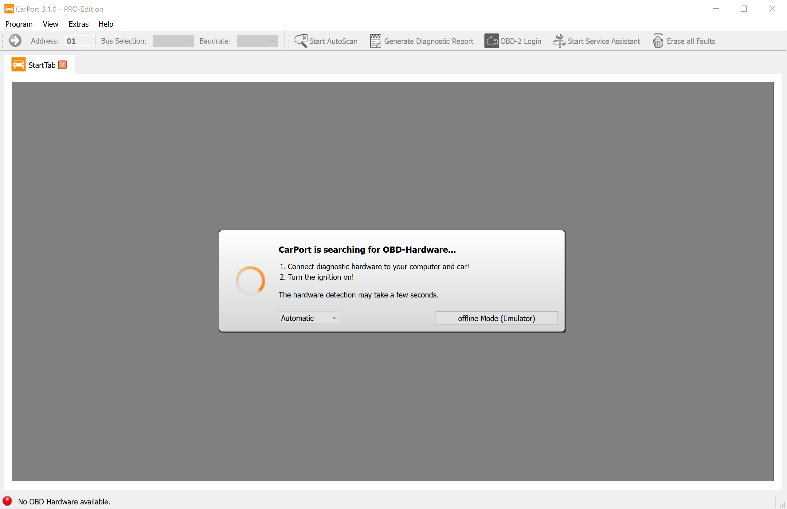
The software automatically begins to search all available interfaces (USB, COM ports) for a connected diagnostic interface. This process usually takes only a few seconds.
Important notes on connection:
- Order: Ideally, connect the interface first to the vehicle (OBD port) and then to the USB port of your laptop.
- KKL interfaces: Pure KKL adapters (e.g., AutoDia K409) strictly require power supply from the vehicle to be recognized. Without being connected to the car, the search will not find this interface.
- Ignition: Switch on the vehicle's ignition so that the control units are active and responsive.
Offline Mode (Emulator)
You have the option to explore CarPort even without a connected
diagnostic interface and without a vehicle. Click on
Offline Mode (Emulator) to start a simulation. CarPort will
then behave as if it were connected to a (virtual) VW Golf 4. This is
excellent for getting to know the menus and functions without any risk.
Note: The emulator simulates an older KWP1281 vehicle. Newer UDS
functions cannot be tested here.
Start Screen
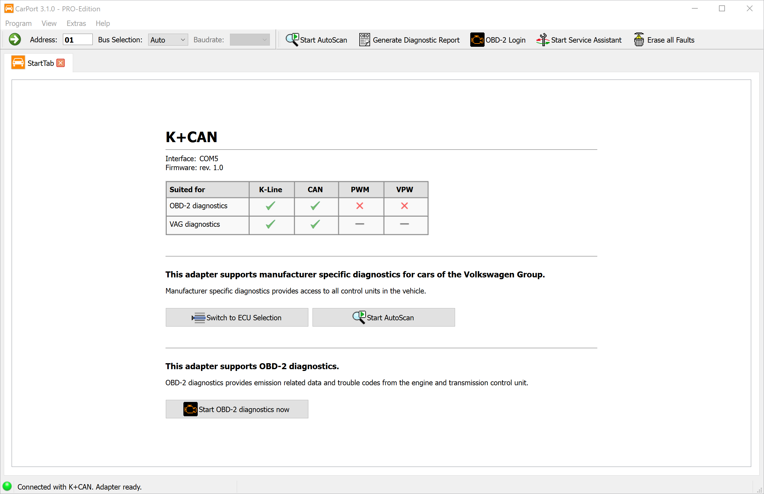
As soon as an interface is found, CarPort displays its properties and capabilities in an overview. From here, you have three options to proceed:
- ECU selection: The direct way to access a specific system (e.g., engine).
- AutoScan: An automatic complete check of all vehicle systems (see AutoScan).
- OBD2 Diagnostics: Start the generic OBD2 diagnostics.
💡 Note: With pure OBD2 interfaces (e.g., ELM327), the ECU selection and AutoScan are not available, as these adapters technically only allow access to OBD2 diagnostics.
ECU Selection
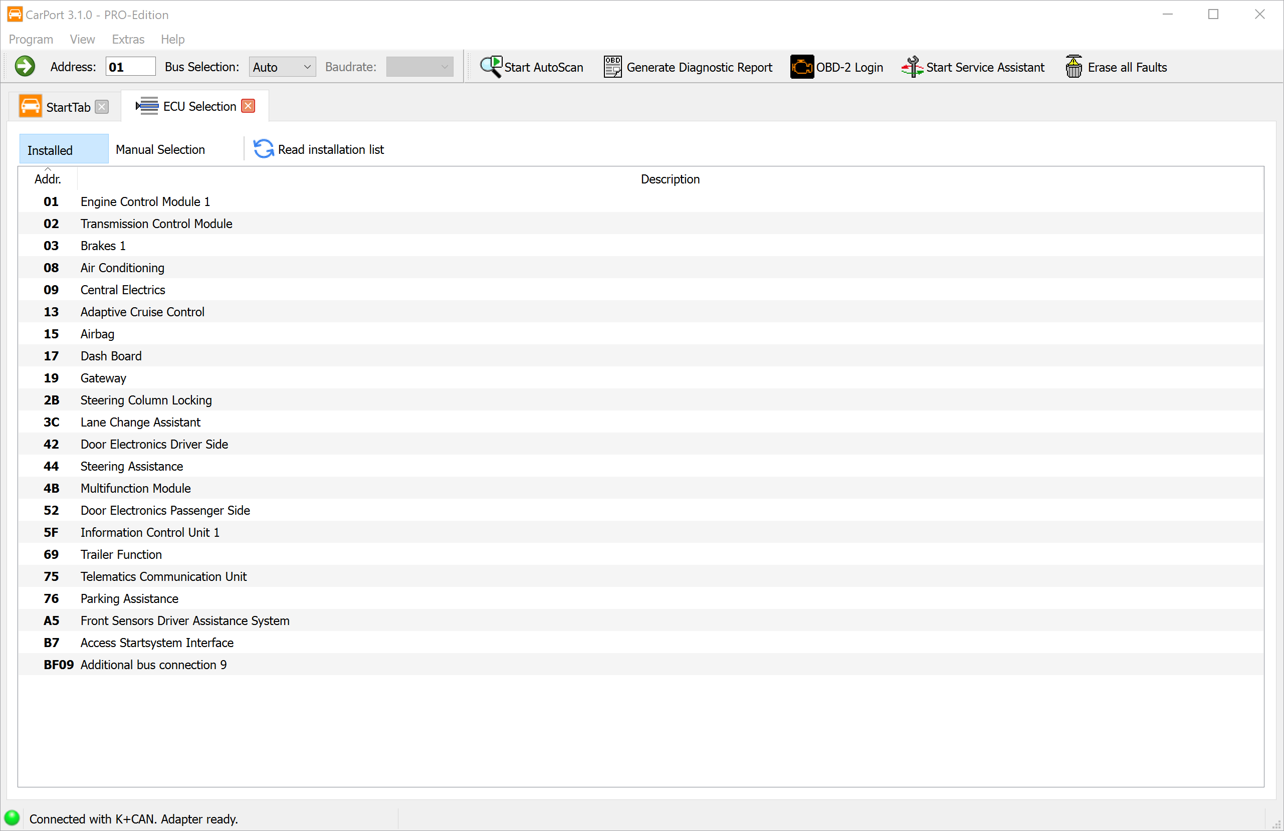
The ECU Selection tab is your control center for
establishing connections to the individual vehicle systems.
Automatic Installation List (Installed tab)
In modern vehicles (with a CAN gateway), CarPort automatically queries the central gateway to find out which ECUs are installed in the car.
- Advantage: You only see the ECUs that your vehicle actually has.
- Operation: A double-click on an
entry (e.g.,
01 - Engine Electronics) establishes the connection. - Update: You can restart the query using the
Read installation listbutton.
Manual Selection (Manual Selection tab)
For older vehicles (K-line without a gateway) or if automatic detection fails, use this tab.
- Select your vehicle model (or a generic scan list) at the top.
- CarPort now displays all possible ECUs for this model.
- Connect by double-clicking.
(Note: Since no verification takes place here, you might try to open ECUs that do not exist in your equipment variant. CarPort will then report a connection error.)
Establishing a Connection
As soon as you have selected an ECU by double-clicking, CarPort attempts to establish communication. After a successful connection, a new tab opens for the respective ECU, and you have access to all diagnostic functions.
In the toolbar, you can additionally select how the connection should
be established via Bus Selection:. The available options
are Auto (automatic detection), K-Line, and
CAN. When manually selecting the K-line, the baud
rate can also be set. Usually, the Auto setting is
the right choice – manual selection is only necessary in exceptional
cases, such as communication problems or special ECUs.
💡 Tip:
You can also type the address of an ECU (e.g., 17 for
Instrument Cluster/Speedometer) directly into the input field in the
upper toolbar and press Enter to connect.
Diagnostic Functions (Basic)
This chapter covers the basic functions that are essential for daily diagnostic work. These functions are "read-only", meaning they do not change any configuration in the vehicle and can therefore be executed without risk.
AutoScan
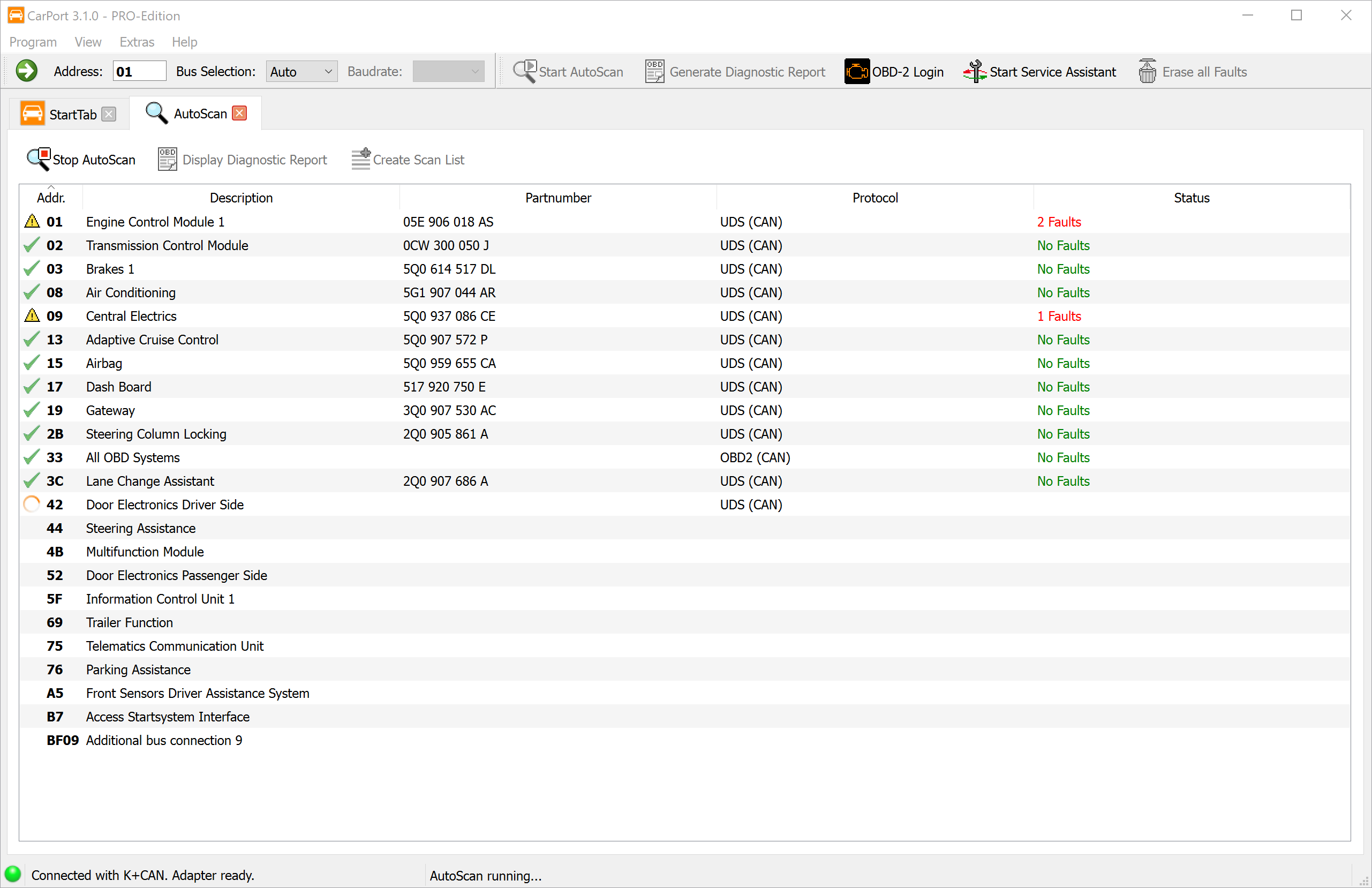
The AutoScan is the ideal starting point for any diagnostic session. It automatically checks all control modules installed in the vehicle for faults and provides a comprehensive status report.
How it works: The technical process of the scan differs depending on the vehicle generation:
Vehicles with a diagnostic gateway (CAN bus): CarPort first requests the installation list from the gateway. This list (usually) contains exactly the control modules that are configured in the vehicle. Subsequently, only these specific control modules are queried. This enables a very fast scanning process (often under 2 minutes).
Vehicles without a gateway (K-line): Here, there is no central list of installed components. CarPort must therefore attempt to address every theoretically possible control module one after the other. Since the program has to wait for a timeout for each non-existent control module, this process can take a very long time (10 minutes and longer).
💡 Tip: For vehicles without a gateway, use scan lists to massively speed up the process.
Starting the AutoScan: Click on
AutoScan on the start screen or in the toolbar. If
automatic detection is not possible (older vehicles), you will be
prompted to select the vehicle (e.g., Golf 4 (1J)).
Diagnostic Report
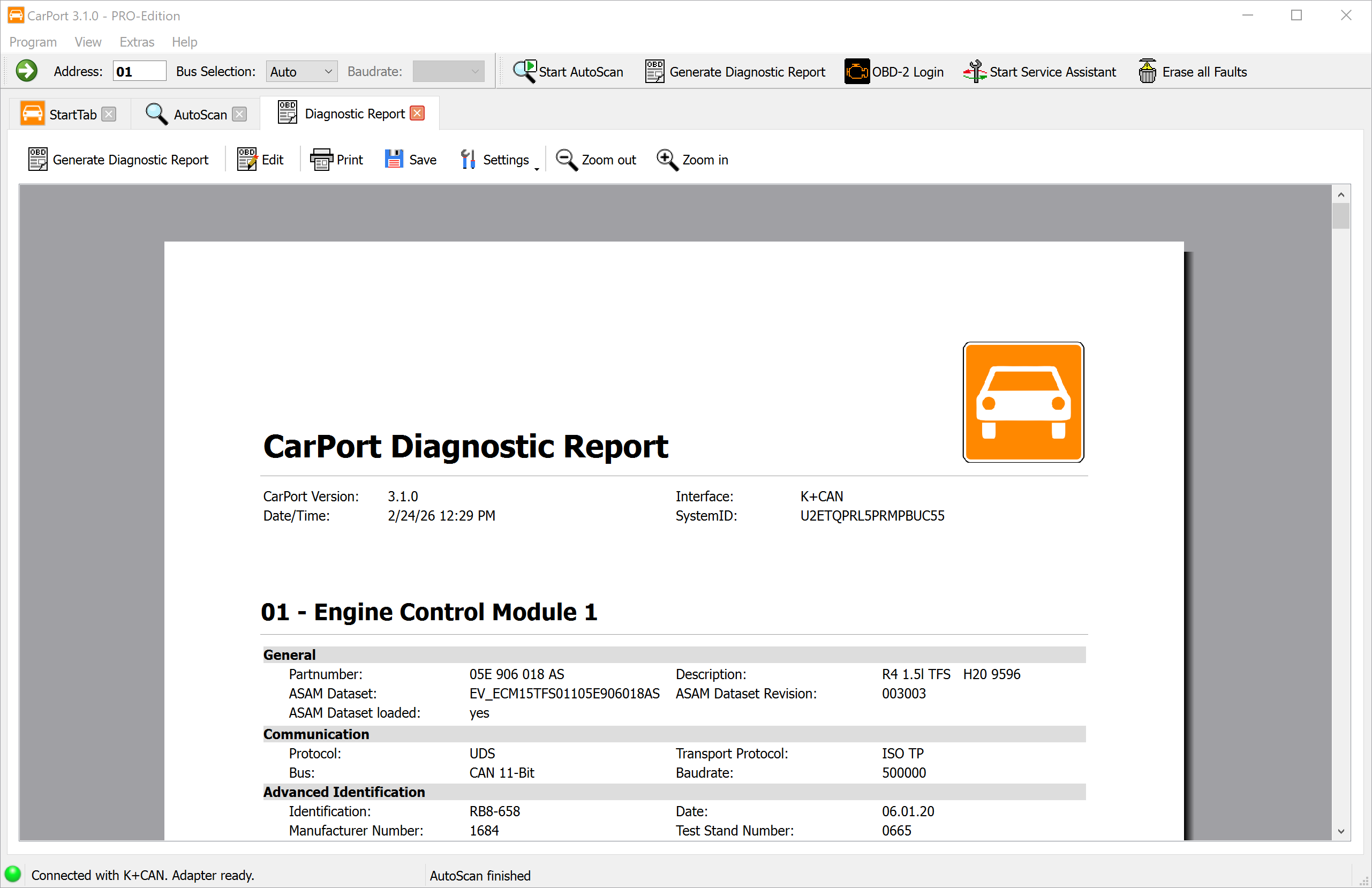
After the AutoScan is complete, you can display the result as a professional diagnostic report. The report contains the following information:
- Header data: CarPort version, date and time, interface used, and system ID.
- Control modules: All detected control modules are listed in ascending order by address – each with its information (part number, description, etc.) and the corresponding fault codes in plain text.
Customizing the report:
- Via
Settings, you determine which data the report should contain (control module info and/or fault codes). You can also adjust the font size to your needs. - Via
Edit, you switch to edit mode to individually supplement the report – e.g., with your own notes, customer data, or repair instructions.
Exporting and printing:
- Click on
Printto print the report directly. - Click on
Saveto save the report as a PDF file.
💡 Tip: The diagnostic report is ideal as your own documentation, as proof for workshops and insurance companies, or to get targeted, qualified help in forums.
Scan Lists
For older vehicles (K-line), you can define which control modules should be queried during the AutoScan in order to save time.
Creating a scan list:
- Perform a complete AutoScan once via the model selection.
- When the scan is complete, click on
Create Scan List. - Give the list a name. Optionally, you can link the detected Vehicle Identification Number (VIN) to the list. Effect: The next time this vehicle is connected, CarPort detects the VIN and automatically selects the optimized scan list.
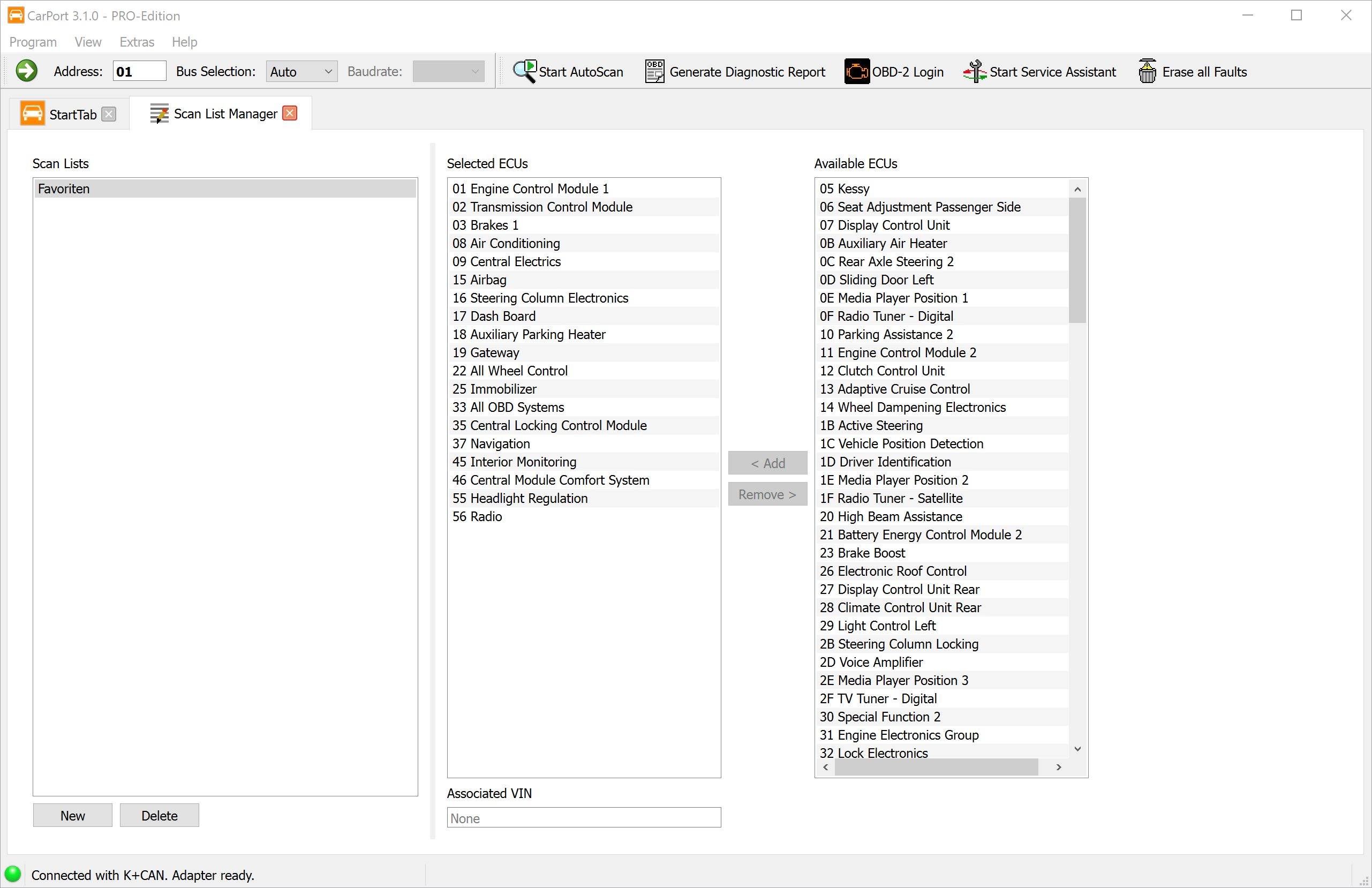
You can also manage scan lists manually via the menu
Extras → Scan List Manager.
Info
As soon as you have opened a control module, the Info
tab displays the most important information about this control
module.
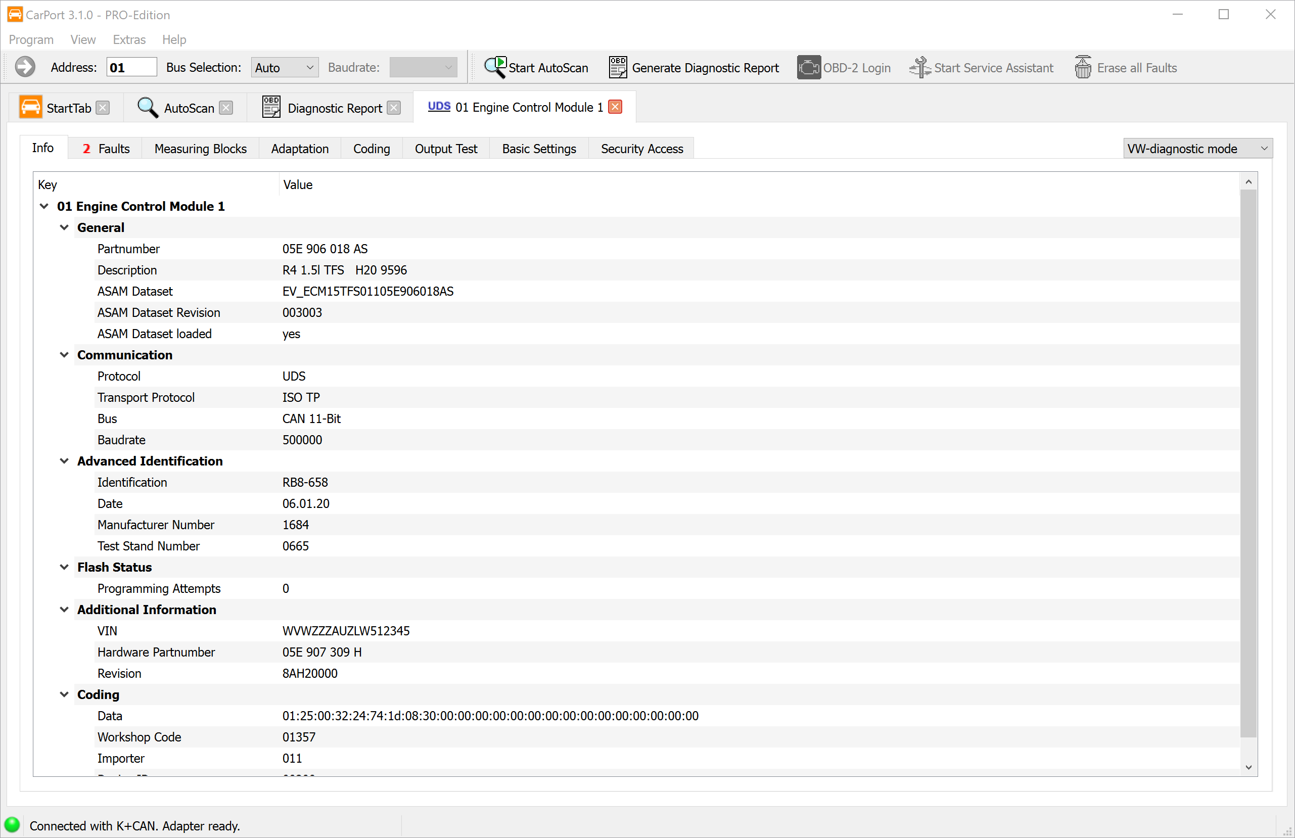
The displayed data varies depending on the protocol and control module, but always includes:
- Part number: The unique identifier of the control
module (e.g.,
05E 906 018 AS). - Description: Designation of the control module
(e.g.,
R4 1.5l TFS). - ASAM dataset (UDS only): Important for identifying the correct control module description data (ODX data).
- Communication data: Information about the bus and protocol used.
You can select any rows and copy them to the clipboard using
Ctrl+C or via the context menu.
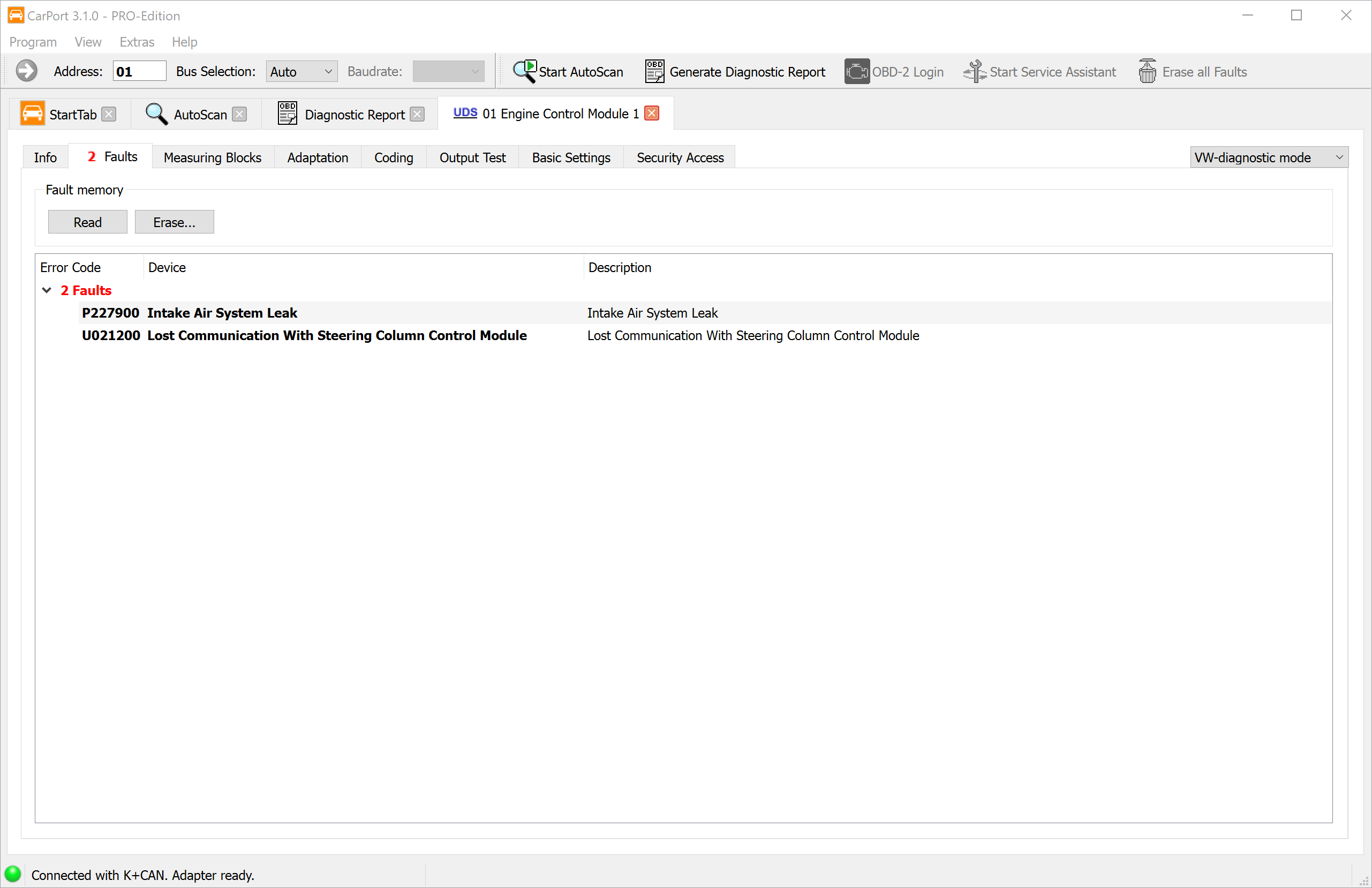
Faults
The fault memory is the most important tool for fault diagnosis. This is where the control module stores detected irregularities that can help you with troubleshooting.
The fault code (DTC - Diagnostic Trouble Code) is stored in a
standardized format, e.g., P0100 or 16485.
CarPort reads these codes and displays them in plain text so that you
immediately understand which component is affected and what type of
fault is present.
The display includes:
- Error Code: The standardized code (e.g.,
P0100or16485). - Device: Plain text description of the affected
component (e.g.,
Mass air flow sensor). - Description: Plain text description of the fault
(e.g.,
no communicationorupper limit exceeded), optionally with fault status (intermittent,static)
ℹ️ Background knowledge:
Many fault codes begin with a letter that indicates the fault category:
- P: Powertrain (drive, engine, transmission)
- B: Body (bodywork, comfort, airbag)
- C: Chassis (suspension, brakes)
- U: User-Network (communication between control modules)
Environmental conditions (Freeze Frames):
With modern protocols (KWP2000, UDS), the control module additionally stores the accompanying circumstances at the time of the fault. The data corresponds in form and meaning to the live measuring values (e.g., engine speed, temperature, load) and provides important clues to the cause of the fault.
The freeze frame data is displayed when you expand the tree view
(click on > in front of the fault code or double-click
on the fault code).
Actions:
Erase...: Clears the fault memory after confirmation. All fault codes and associated data are removed. The control module immediately begins re-evaluating the system status.Read: Reads the fault memory again to update the current status.
💡 After clearing, the fault memory is automatically read again a few seconds later to update the status. If the fault condition persists, the fault code will reappear immediately. You must first fix the underlying problem for the fault to disappear permanently.
Measuring Blocks
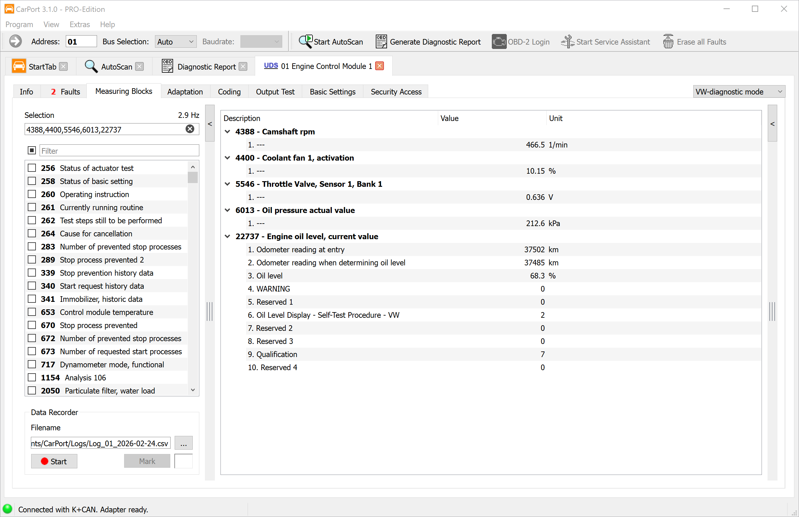
The measuring value display allows you to view live data from a control module in real time. This enables you to monitor sensor and actuator data during operation and identify correlations between different parameters – an indispensable tool for dynamic fault analysis.
Depending on the control module, measuring values include:
- Physical quantities: Temperature, pressure, voltage, RPM, speed
- Status information: Switching states, fault flags, operating modes
- Text values: Vehicle identification number, software version
- Raw values: Bit or byte fields without physical conversion
The presentation and organization of the measuring values differ significantly depending on the diagnostic protocol.
KWP1281 / KWP2000
In older vehicles, the data is organized into numbered measuring blocks. Each block contains 4 individual values that (usually) belong together thematically (e.g., Block 1: Engine speed, coolant temperature, lambda sensor, engine load).
- KWP1281: Blocks 0 to 255 – special case Block 0: contains 10 values instead of 4.
- KWP2000: Blocks 1 to 254.
- If no description data is available for the control module, CarPort automatically scans all blocks and displays the available values. The naming is then generic based on the physical quantity (e.g., "Temperature", "RPM", "Voltage").
UDS
In modern control modules with the UDS protocol, the rigid 4-value grouping is dissolved. Any number of measuring values can be hidden behind each identifier. CarPort uses the ODX description data (ASAM dataset) of the respective control module to display the available values with plain text names, units, and conversion formulas.
Selecting Measuring Values
Any number of blocks can be displayed simultaneously. The values are updated cyclically – the more blocks are active, the lower the update rate per value. The measuring values can be selected in several ways:
- Checkbox: Activate individual measuring values or blocks by checking the box.
- Direct number entry: Enter block numbers as a
comma-separated list or as a range with a hyphen, e.g.,
1,2,4-7,10-14. - Text filter: Type a search term into the filter field to narrow down the displayed list (e.g., "Boost pressure" only displays measuring values whose name contains this term).
Graphical Display
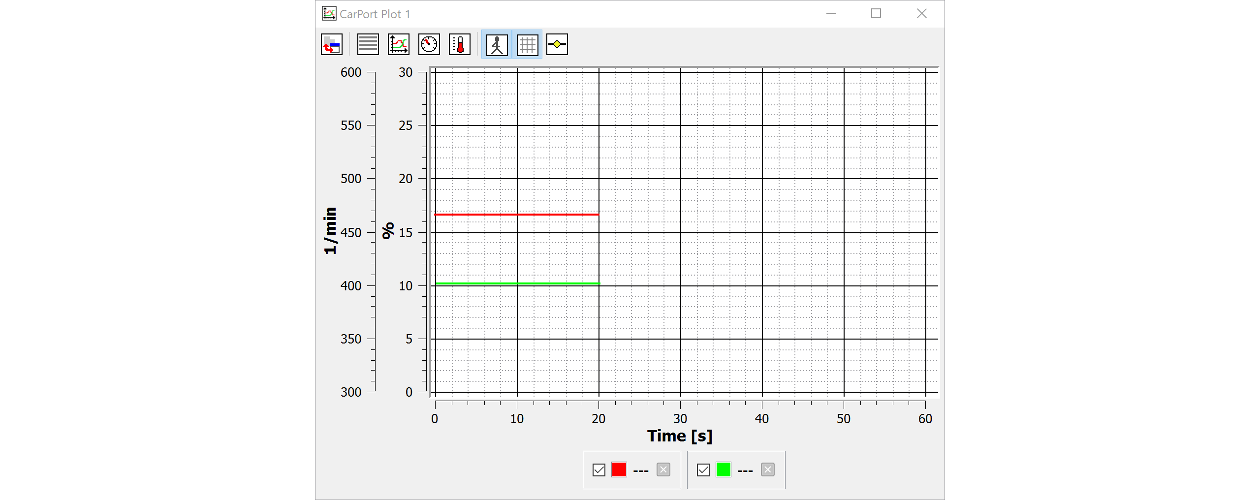
If you want to visualize the progression of values over time (e.g., specified vs. actual boost pressure, temperatures during a test drive), you can use the integrated plot function.
Adding measuring values to the plot:
- Double-clicking on a displayed measuring value automatically adds it to the current plot. If no plot is open yet, a new plot window is created.
- Via the context menu (right-click on a measuring value), you can specifically add the value to a certain plot window.
- Multiple plot windows can be open simultaneously to display different groups of values separately.
Display modes:
You can switch between different display modes via the toolbar in the plot window:
- Graph: Line chart with a time axis (default) – ideal for trend analysis.
- List: Tabular display of the current values.
- Instruments: Round instrument display (speedometer look) – well suited for individual values such as RPM or speed.
- Thermometer: Bar display – clear for temperature or percentage values.
Operating the graph:
- Use the mouse wheel to zoom into the time axis.
- Click and drag to move the visible area.
Data Recording (Logging)
For test drives or longer monitoring sessions, you can record measuring values in a CSV file and subsequently evaluate them in external programs.
Step-by-step guide:
- Select the desired measuring values.
- In the
Data Recorderarea, select the save location and file name. By default, the folder defined in the settings is used; the file name automatically includes a timestamp. - Click on
Startto start the recording. - The recording runs until you press
Stop. - During the recording, you can set markers to
highlight special points (e.g., "Full throttle", "Idle", "Fault
symptom"). Enter the desired text into the input field and click on
Mark.
The generated CSV file can be evaluated in Excel or specialized programs like MegaLogViewer.
ℹ️
Note on the CSV separator: CarPort automatically adapts
the separator to the regional setting of your operating system
(semicolon ; for German settings, comma , for
English settings) so that the file can be opened directly in Excel. The
separator can be set manually in the settings if required.
OBD2 Diagnostics
OBD2 (On-Board Diagnostics, Generation 2) is a legally required, cross-manufacturer diagnostic interface that is present in all vehicles with a gasoline engine from model year 2001 and with a diesel engine from model year 2004 (EU region). In contrast to VAG-specific diagnostics, which use proprietary protocols, OBD2 is based on internationally standardized norms (ISO 15031, SAE J1979).
The purpose of OBD2 is primarily the monitoring of emissions-related systems. The interface provides access to the engine control module and – if present – the transmission electronics. The available scope of data is limited to:
- Emissions-related fault codes (DTCs in P0xxx format)
- Emissions-related measuring values (e.g., engine speed, coolant temperature, lambda sensor values)
- Readiness status of the emissions monitoring systems
- Freeze frame data at the time of a detected fault
ℹ️ Important: OBD2 does not provide access to manufacturer-specific control modules such as ABS, airbag, comfort electronics, or infotainment. For full access to all vehicle systems, use the VAG-specific diagnostics with a compatible interface.
Starting OBD2 Diagnostics
There are several ways to start OBD2 diagnostics in CarPort:
- Via the start screen: After interface detection,
click on the
Start OBD-2 diagnostics nowbutton (see Start Screen). - Via the toolbar: Use the
OBD-2 Loginbutton in the upper toolbar. - Via the control module address: Enter the address
33into the address field of the toolbar and confirm withEnter.
💡 Note: With pure OBD2 interfaces (e.g., ELM327, OBDLink), OBD2 diagnostics is the only available function. Control module selection and AutoScan are not available with these adapters.
Reading and Clearing Fault Codes
OBD2 diagnostics allows reading and clearing of emissions-related fault codes. The functionality corresponds to the process described under Fault Codes, but is limited to the standardized OBD2 scope:
- Only standardized fault codes in the format
P0xxx/P2xxx/P3xxxare displayed. - Manufacturer-specific codes (e.g., in VAG's own format
16xxx) are not accessible via OBD2. - Freeze frame data can be viewed – provided it is supplied by the vehicle.
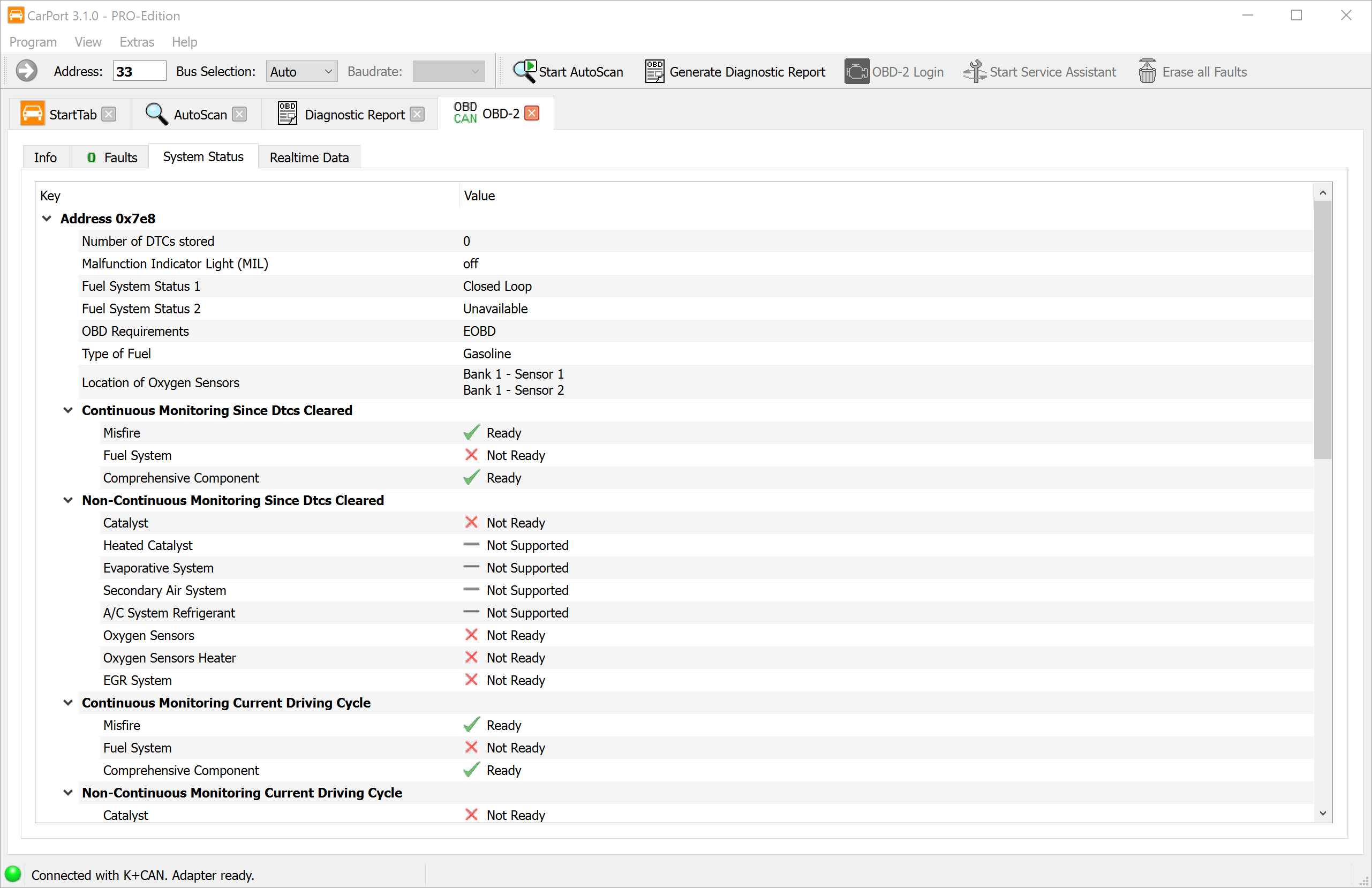
Readiness Status
The readiness status indicates whether the vehicle's internal monitoring systems (monitors) have successfully completed their self-tests since the fault memory was last cleared. This is particularly relevant for the emissions test, as many testing centers require a complete readiness status as a prerequisite.
CarPort clearly displays the status of each monitor:
- Completed (ready): The monitor has run through its test cycle and found no faults.
- Not completed (not ready): The monitor has not yet completed its test cycle since the fault memory was last cleared. The necessary driving conditions have not yet been met.
- Not supported: The vehicle does not have this monitoring system (e.g., no secondary air system installed).
Typical monitors include:
| Monitor | Description |
|---|---|
| Catalytic converter | Check of conversion efficiency |
| Heated catalytic converters | Check of heating function |
| Fuel system | Monitoring of mixture control |
| Lambda sensors | Functional check of exhaust sensors |
| Lambda sensor heater | Check of heating circuits |
| Misfire | Detection of engine misfires |
| Secondary air system | Check of secondary air injection |
| Evaporative emission system (EVAP) | Leak test of the fuel vapor system |
| EGR system | Functional check of exhaust gas recirculation |
💡 Tip: After clearing the fault memory, all monitors are reset to "not completed". To restore the readiness status, the vehicle-specific drive cycles must be completed. Depending on the monitor, this may require several trips under specific conditions (city driving, highway driving, cold start).
Live Data (PIDs)
OBD2 provides real-time measuring values via so-called PIDs (Parameter IDs). These standardized identifiers define which sensor data the engine control module returns upon request. CarPort automatically queries the available PIDs and displays the supported values with plain text designations and physical units.
Frequently available PIDs are, for example:
- Engine speed (RPM)
- Vehicle speed (km/h)
- Coolant temperature (°C)
- Intake air temperature (°C)
- Engine load (%)
- Lambda sensor values (Voltage / Ratio)
- Fuel pressure (kPa)
- Ignition timing (° BTDC)
- Short-term and long-term fuel trim (%)
The display and operation of the live data correspond to the procedure described under Measuring Blocks. You can select values, visualize them in the graph, and record them via logging.
ℹ️ Note: Which PIDs a vehicle actually supports varies depending on the manufacturer, model, and year of manufacture. Not every vehicle provides all standardized PIDs.
Differences to VAG-specific Diagnostics
OBD2 diagnostics and VAG-specific diagnostics complement each other, but differ fundamentally in scope and possibilities:
| Feature | OBD2 Diagnostics | VAG-specific Diagnostics |
|---|---|---|
| Access to control modules | only engine and possibly transmission | all installed control modules |
| Fault codes | only emissions-related fault codes | complete fault memory of all systems |
| Measuring values | standardized PIDs | all manufacturer-specific measuring values |
| Coding | not available | available |
| Adaptation | not available | available |
| Output test | not available | available |
| Basic settings | not available | available |
| Control module selection | not available (fixed address) | all addresses selectable |
| AutoScan | not available | available |
| Required interface | any OBD2 interface (e.g., ELM327) | VAG-compatible interface (e.g., AutoDia K509, K+CAN Commander 1.4) |
When to use OBD2?
- You only own an OBD2 interface (e.g., ELM327, OBDLink).
- You want to quickly check the Malfunction Indicator Lamp (MIL) or check the readiness status before an emissions test.
- You are diagnosing emissions-related problems on the engine.
When to use VAG-specific diagnostics?
- You need access to other control modules (e.g., ABS, airbag, air conditioning, steering).
- You want to perform codings, adaptations, or basic settings.
- You need the complete fault memory across all vehicle systems (AutoScan).
Diagnostic Functions (Advanced)
This chapter covers the advanced diagnostic functions that actively intervene in the configuration or calibration of control units. These functions are "write" operations and change parameters in the vehicle – therefore, only use them if you know what you are doing, and always note down the original values beforehand.
Adaptation
Adaptation allows you to change configurable parameters of a control unit. Unlike Coding, which switches functions on or off, adaptation is used to calibrate or adjust values within an existing function.
Typical use cases for adaptations are:
- Calibration after component replacement: e.g., storing injector quantity values after replacing a fuel injector.
- Adjustment of target values: e.g., idle speed, light sensitivity of the rain/light sensor, sensitivity of the parking assist.
- Activation of functions with parameters: e.g., daytime running light dimming value, coming-home time.
- Resetting service counters: e.g., resetting the service interval display after an oil change.
⚠️ Warning: Adaptations change the behavior of the control unit. Incorrect values can lead to malfunctions or safety-critical misbehavior. Before making any changes, note down the current original value so that you can restore it if necessary.
The procedure and presentation of the adaptation function differ significantly depending on the diagnostic protocol used.
Adaptation in KWP1281 / KWP2000
In the older KWP1281 and KWP2000 protocols, the adaptation parameters are organized into numbered channels:
- KWP1281: Channels 0 to 100
- KWP2000: Channels 0 to 255
Each channel contains a single value. This is usually a 16-bit value (range 0–65535) or an 8-bit value (range 0–255). A special form is the Long Adaptation, where ASCII text values are stored (e.g., injector quantity values as a character string).
Presentation of the channels:
If description data for the control unit is available in CarPort, the channels are displayed with plain text names (e.g., "Idle speed", "Throttle valve adaptation"). In addition, the raw data is converted into physical values with units (e.g., 0–100 % or -50 to +50 °C) or presented as a selection list (e.g., "0 = Off, 1 = On").
If no description data is available, the presentation is generic via
the channel number (e.g., "Adaptation 42") with the unformatted raw
value. The use of description data can be toggled on and off via the
Use label file information if available checkbox to also
allow direct access to the raw values.
Step-by-step guide:
- Select the desired adaptation channel from the list or enter the channel number manually.
- The value currently stored in the control unit is displayed. Note down this value before making any changes.
- Enter the new value into the input field.
- Click on
Testto test the value.- The value is transferred to the volatile memory of the control unit. The control unit uses the new value immediately, but it will be lost upon the next restart.
- If the value is invalid or outside the permissible range, the control unit will display an error message.
- Check whether the desired behavior occurs.
- Click on
Store...to save the value permanently in the control unit.
💡 Tip:
The two-step process (Test → Store) serves as a safety mechanism. As
long as you only use Test, you can return to the original
value at any time by restarting the ignition. Only Store...
makes the change permanent.
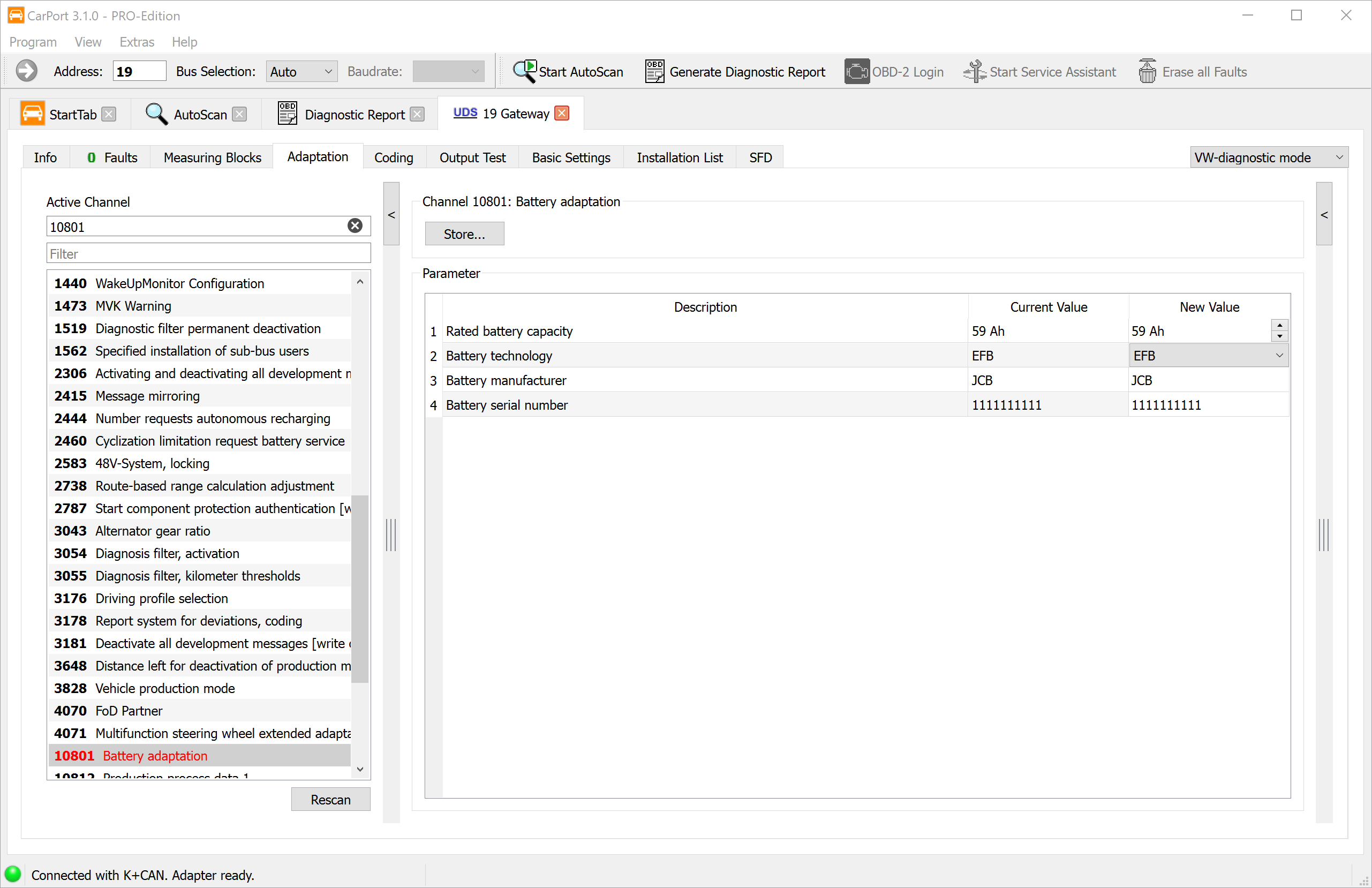
Adaptation in UDS
In modern control units with the UDS protocol, adaptation differs fundamentally:
- Identifiers instead of channel numbers: Adaptation parameters are addressed via 16-bit identifiers. The assignment to a plain text name is done exclusively via ODX description data (ASAM dataset).
- Complex data structures: Adaptation values in UDS can be simple numerical values, but can also include bitfields, character strings, or multi-part structures.
- Direct storing: Unlike KWP1281/KWP2000, there is no separate test step in UDS. Changes are saved immediately and permanently in the control unit upon transmission.
- Description data required: Without the appropriate ODX data, the identifiers and their values cannot be interpreted. CarPort therefore strictly requires the correct description data for the respective control unit.
⚠️ Warning: Since changes are immediately saved permanently in UDS control units, there is no way to test the new value volatilely first. Ensure that the entered value is correct before transmitting it.
Coding
The coding of control units is used to activate, deactivate, or switch between different variants of functions. Every vehicle model is offered with a variety of equipment options that vary depending on the market, model, and standard equipment. The hardware installed is often identical – only the coding of the corresponding control unit determines which functions are actually active.
A typical example: A vehicle is equipped with halogen headlights from the factory, but the hardware also supports Xenon or LED. The coding of the control unit determines which headlight type is installed and how the light control operates. Other common coding changes include, for example:
- Activation or deactivation of the daytime running light function
- Behavior of the central locking system (e.g., automatic locking while driving)
- Mirror lowering when reversing
- Configuration of the convenience turn signal blink count
- Adaptation of the closing assist for electric power windows
⚠️ Warning: Incorrect coding can lead to vehicle functions no longer working correctly or error messages being triggered in the control unit. Before making any changes, note down the current coding value so that you can restore it if necessary.
In the VAG group, a distinction is made between two coding methods. Which method is used depends entirely on the implementation of the control unit.
Short Coding
Short coding uses a simple numerical code (3-, 5-, or 7-digit decimal number) to define the configuration of a control unit. Each digit or group of digits within this code represents a specific set of functions.
- Protocols: Exclusively in KWP1281 and KWP2000.
- Variants and value ranges: Depending on the control unit, one of four variants is used. CarPort automatically detects the type and restricts the permissible input range accordingly:
| Variant | Value range | Digits |
|---|---|---|
| 7-bit | 0–127 | 3-digit |
| 15-bit | 0–32767 | 5-digit |
| 20-bit | 0–1048575 | 7-digit |
| 23-bit | 0–8388607 | 7-digit |
- Presentation: If description data is available, CarPort displays the meaning of each digit or group of digits in plain text (e.g., "Digit 1: Headlight type – 0 = Halogen, 1 = Xenon"). Without description data, the numerical code is displayed without further explanation.
Step-by-step guide (short coding):
- CarPort displays the coding value currently stored in the control unit. Note down this value.
- If description data is available, you can change the individual digits using the displayed selection fields.
- Alternatively, enter the new coding value directly as a number into
the
New Coding:input field. - Click on
Write...to transmit the coding to the control unit.
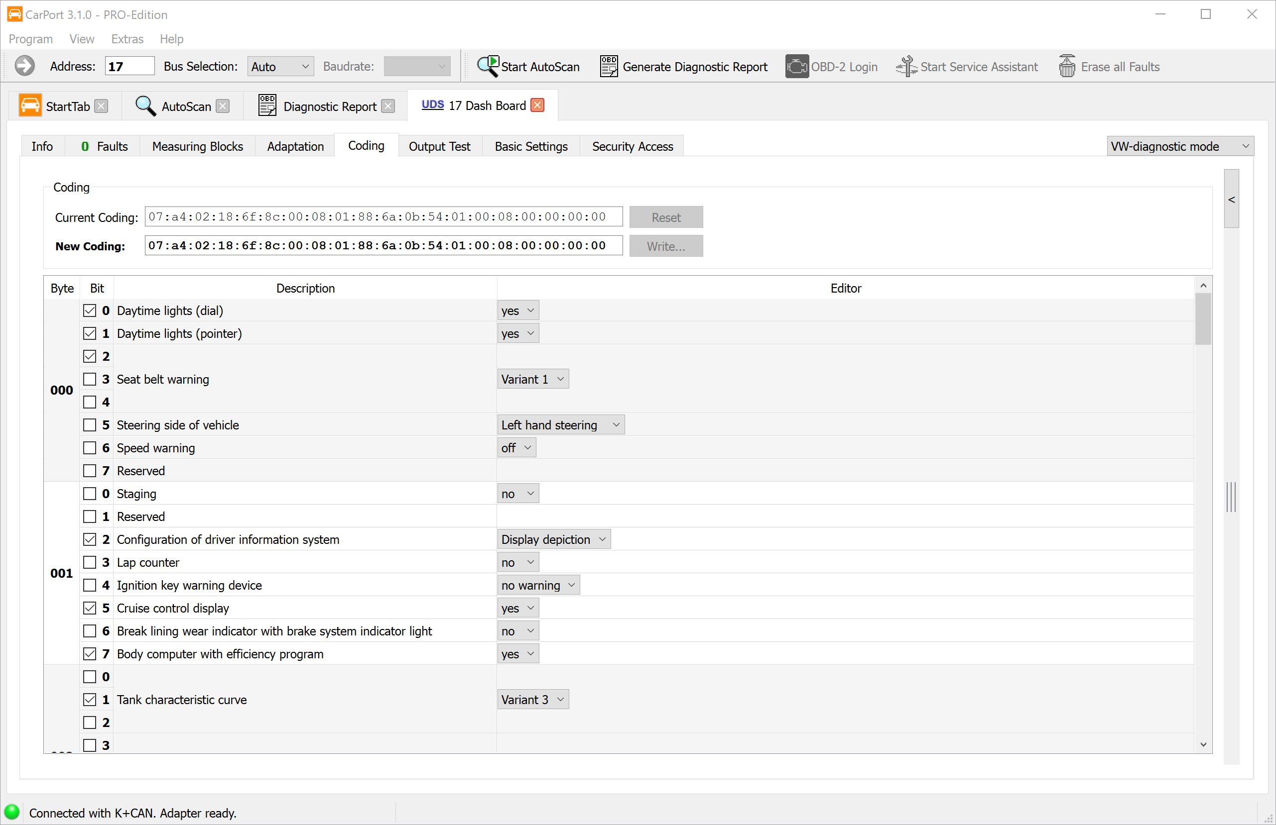
Long Coding
Long coding offers much finer control over the control unit configuration. Instead of a single number, a hexadecimal byte string is used, where each individual bit represents a specific function or parameter.
- Protocols: In KWP2000 and UDS.
- Presentation: The coding is displayed as a sequence
of bytes (e.g.,
0F 3A 00 12 8B). Each byte consists of 8 bits that can be individually set or cleared.
Presentation with and without description data:
If description data for the control unit is available, CarPort displays a plain text description as a checkbox for each bit (e.g., "Daytime running light active", "Mirror lowering when reversing"). You can configure the desired functions by simply checking or unchecking the boxes.
If no description data is available, CarPort displays a generic view with byte and bit numbers (e.g., "Byte 3, Bit 5"). In this case, you must know the meaning of the individual bits from an external source (e.g., vehicle forums, workshop documentation). However, you can change the bits very specifically if you have the corresponding information.
Step-by-step guide (long coding):
- CarPort reads the current coding from the control unit and displays it. Note down the displayed hexadecimal value as a backup. Alternatively, you can also find the coding in the Diagnostic Report.
- Activate or deactivate the desired functions using the selection
fields (if description data is available), or change the bit values via
the checkboxes, or write entire byte values directly into the
New Coding:input field. - Click on
Write...to transmit the new coding to the control unit.
💡 Tip: In the byte view, you can edit individual bytes directly as hexadecimal values. The checkbox presentation updates automatically and vice versa – both views are always synchronized.
Coding and Security Access
Some control units require a Security Access before writing a new coding. In this case, CarPort will prompt you to enter the required access code before transmission. In newer vehicles with SFD (Vehicle Diagnostic Protection), coding changes may additionally be restricted by cryptographic protection mechanisms.
Output Test
The output test allows the targeted activation of individual actuators of a control unit to check their electromechanical function isolated from normal driving operation. Actuators are all components that are actively controlled by the control unit to perform a physical action – e.g., valves, relays, electric motors, lights, or solenoid valves.
Typical use cases:
- Troubleshooting: Checking whether an actuator responds to activation (e.g., does a relay click, does a motor turn?).
- Function check after repair: Ensuring that a newly installed component works correctly.
- Leak testing: Targeted activation of individual valves for pressure testing.
⚠️ Warning: During an output test, actuators are activated independently of the normal control loop. Ensure that the vehicle is safely parked and no persons are endangered. Some tests (e.g., radiator fan run-on, fuel pump) can lead to unexpected movements or noises.
Depending on the diagnostic protocol, CarPort distinguishes between two operating modes: the sequential and the selective output test.
Sequential Output Test (KWP1281 / KWP2000)
In the sequential output test, the control unit activates all available actuators one after the other in a fixed, predetermined sequence. You can step through the individual actuators one by one and observe their reaction.
Step-by-step guide:
- Open the Output Test tab in the connected control unit.
- The first actuator in the sequence is activated automatically. CarPort displays the name of the currently activated actuator (if description data is available).
- Observe the vehicle's reaction (e.g., clicking of a relay, movement of a flap, lighting up of a lamp).
- Click on
Nextto advance to the next actuator in the sequence. - To activate an actuator again, click on
Activate. - If available, accompanying measuring values are displayed, providing information about the status of the actuator (e.g., current consumption, feedback signal).
💡 Note: The sequence and number of available actuators are determined entirely by the control unit and cannot be influenced.
Selective Output Test (KWP2000 / UDS)
The selective output test allows the targeted selection and individual activation of specific actuators without having to go through the entire sequence. This is particularly efficient when only a specific component needs to be tested.
In KWP2000:
- Click on
Start Scan...to determine the actuators supported by the control unit. CarPort scans the available tests and displays them in a list. - Select the desired output test from the list.
- Start the test via
Start. - Observe the reaction and the displayed measuring values (if available).
- End the test via
Stop.
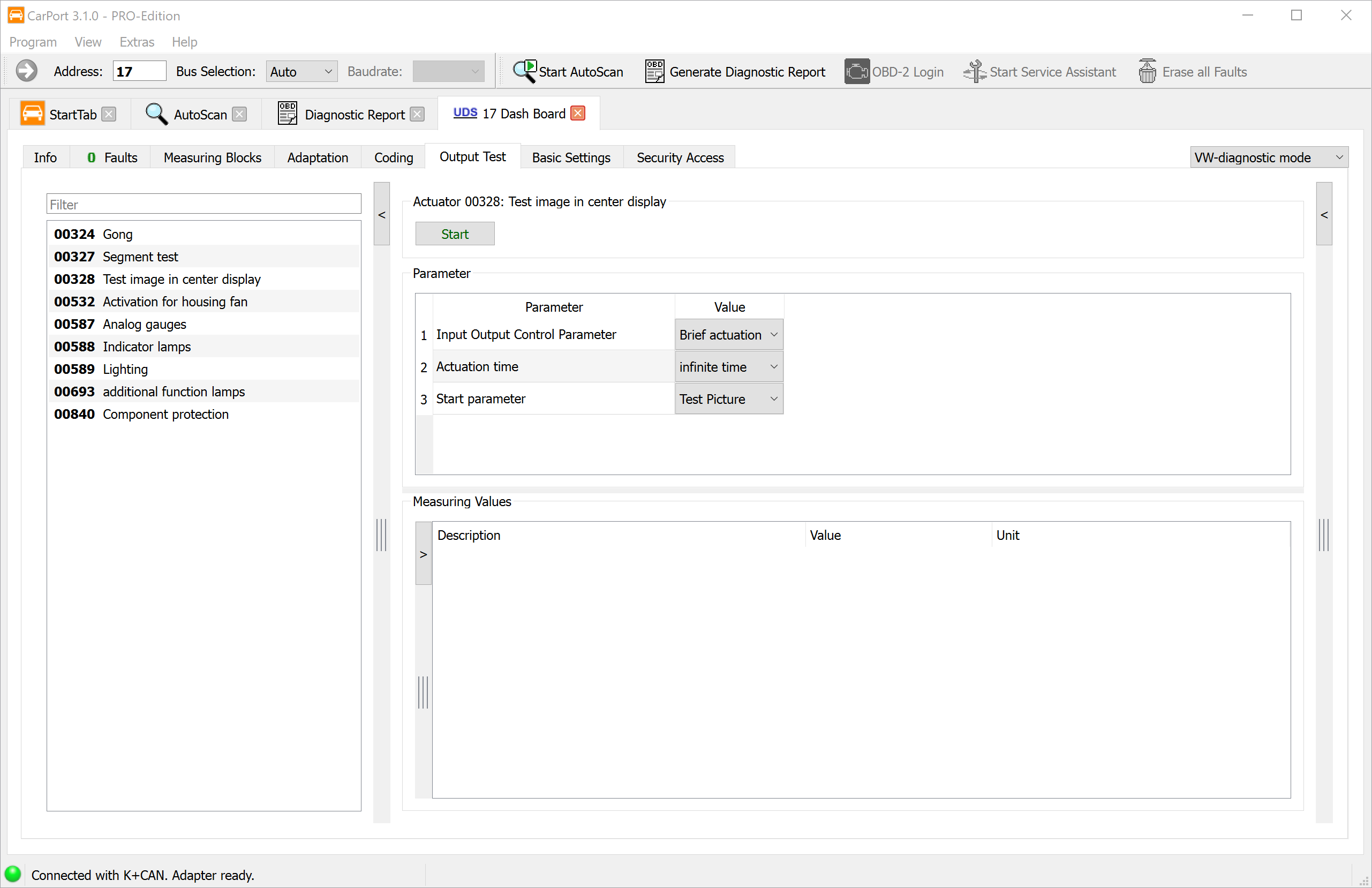
In UDS:
In modern control units with the UDS protocol, advanced options are available:
- CarPort automatically determines the available output tests based on the ODX description data and displays them with plain text names in a list.
- Select the desired test.
- Depending on the actuator, parameters for activation can be set (e.g., duration, intensity, direction) – the available scope depends on the respective control unit.
- Start the test via
Startand end it viaStop.
Measuring values during the test (UDS):
During an ongoing output test, CarPort automatically displays status information, provided the control unit supplies it:
| Measuring value | Description |
|---|---|
| Status of the output test | Current state (running, finished, aborted) |
| Operating instruction | Instructions from the control unit to the user |
| Currently running routine | Name of the active test routine |
| Current test step | Position within a multi-step test |
| Test steps still to be performed | Remaining steps until completion |
| Cause for abort | Reason if the test was ended prematurely |
In addition, you can add your own measuring values for monitoring (e.g., current consumption, temperature, error flags) to observe further diagnostic data during the test.
End of the output test:
After all test steps have been completed, CarPort displays the message Output Test finished. If the test is aborted prematurely by the control unit (e.g., due to a detected error or a safety shutdown), the message Output Test aborted by ECU appears.
Basic Settings
Basic Settings instructs a control unit to perform an initialization or calibration routine. In doing so, the control unit brings a mechanical or electronic component into a defined initial state or relearns its current position or characteristic values.
Unlike Adaptation, where you manually change values, Basic Settings performs an automated process within the control unit itself. CarPort merely gives the start command – the actual calibration is handled autonomously by the control unit.
When are Basic Settings necessary?
Basic Settings are typically required after the replacement or repair of components so that the control unit correctly recognizes and calibrates the new components. Common use cases are:
- Throttle valve adaptation: After replacing or cleaning the throttle valve, the control unit must remeasure the mechanical stop positions (fully closed / fully open).
- Steering angle sensor calibration: After work on the steering or suspension, the zero point of the steering angle sensor must be relearned so that ESP and driver assistance systems work correctly.
- Electronic Parking Brake (EPB): Before changing brake pads, the parking brake must be put into maintenance mode (retract pistons). After installation, it is reactivated and calibrated via Basic Settings.
- Bleeding the cooling circuit: After filling the cooling system (e.g., after a radiator change or timing belt change), the control unit starts an automatic bleeding cycle in which the pump and valves convey air bubbles out of the circuit.
⚠️ Warning: Basic Settings actively intervene in the control unit function. Especially with safety-relevant systems (brakes, steering, airbag), incorrect routines or routines performed at the wrong time can lead to dangerous conditions. Only perform Basic Settings if you know which routine you are starting, and observe the prerequisites (e.g., engine off, steering in straight-ahead position, vehicle on a level surface).
The procedure differs depending on the diagnostic protocol.
Basic Settings in KWP1281 / KWP2000
In the older protocols, Basic Settings are organized into numbered blocks – analogous to the Measuring Blocks.
Step-by-step guide:
- Select the desired block from the list or enter the block number manually (if no description data is available).
- Click on
Start.- KWP1281: CarPort first reads out the measuring values of the selected block and displays them. These values are usually directly related to the Basic Settings and serve to monitor the process.
- KWP2000: CarPort starts the routine on the control unit without immediately activating the Basic Settings. If available, accompanying measuring values are displayed.
- Click on
Activateto activate the actual Basic Settings. The control unit now performs the necessary calibration steps (e.g., driving the throttle valve to its stops, measuring sensor values). - Observe the displayed measuring values to track the progress and the result of the Basic Settings.
- Upon completion, CarPort displays the message Basic Settings finished.
- Click on
Deactivateto end the Basic Settings and return to the normal operating mode.
💡 Special
feature in KWP1281: Using the Next Block button,
you can switch directly to the next block without leaving the Basic
Settings. In some control units, the blocks must be processed in a
specific sequence because they are interdependent.
Please refer to the instructions in the description data or the workshop
documentation for this.
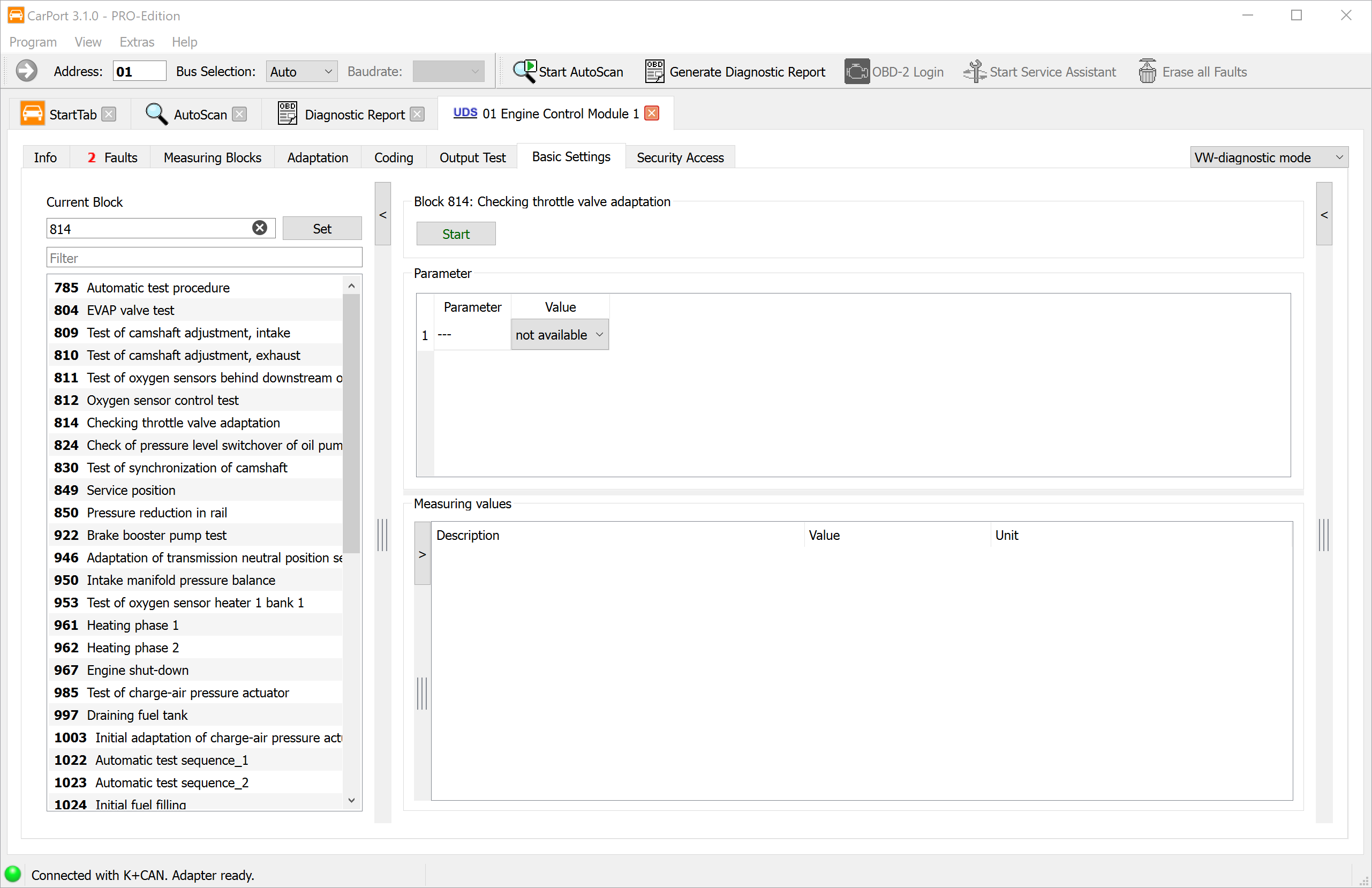
Basic Settings in UDS
In control units with the UDS protocol, Basic Settings are stored as named routines in the ODX description data.
Step-by-step guide:
- CarPort displays the available Basic Settings from the ODX data with plain text names (e.g., "Throttle valve adaptation", "Steering angle sensor calibration"). Select the desired routine.
- Click on
Startto start the routine. The Basic Settings become active immediately – there is no separate activation step as in KWP1281/KWP2000. - Monitor the progress using the displayed measuring values.
- After successful completion, CarPort displays the message Basic Settings finished.
Measuring values during Basic Settings (UDS):
Analogous to the Output Test, CarPort automatically displays status information during ongoing Basic Settings, provided the control unit supplies it:
| Measuring value | Description |
|---|---|
| Status of the Basic Settings | Current state (running, finished, aborted) |
| Operating instruction | Instructions from the control unit to the user (e.g., "Turn steering wheel to the left") |
| Currently running routine | Name of the active calibration routine |
| Current test step | Position within a multi-step process |
| Test steps still to be performed | Remaining steps until completion |
| Cause for abort | Reason if the routine was ended prematurely |
In addition, you can add your own measuring values for monitoring (e.g., engine speed, temperature, sensor values) to keep an eye on other relevant parameters during the Basic Settings.
Aborting and Error Messages
The Basic Settings can be manually aborted at any
time via the Stop button. If the control unit aborts the
routine independently (e.g., due to unfulfilled prerequisites or a
detected error), the message Basic Settings aborted by ECU
appears. In this case, you should check the displayed measuring values
and the fault memory to determine the cause.
Installation List
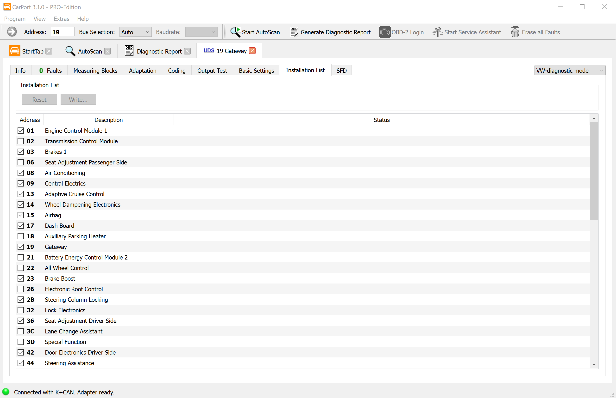
The Installation List is a directory stored in the diagnostic gateway (address 19) of all control units installed in the vehicle. It serves as a central reference for which electronic systems are present in the vehicle.
ℹ️ Note: The Installation List is exclusively available in vehicles with a CAN bus diagnostic gateway. Older vehicles with pure K-line diagnostics do not have a gateway and therefore no Installation List.
Significance of the Installation List:
The Installation List is used by CarPort in several places:
- Control Unit
Selection: In the
Installedtab, CarPort only displays the control units that are registered as installed in the Installation List. - AutoScan: During the automatic fault scan, the control units listed in the Installation List are specifically queried, which significantly speeds up the scanning process.
When does the Installation List need to be adjusted?
As a rule, the Installation List matches the actual vehicle equipment. However, there are situations where manual adjustment is necessary:
- Subsequent installation of components: e.g., trailer hitch with its own control unit, retrofitting an auxiliary heater or a rearview camera.
- Removal of control units: e.g., removal of a system that is no longer needed.
- Missing or incorrect entries: In rare cases, the factory Installation List may be incomplete or incorrect.
If a control unit is physically installed but not registered in the
Installation List, it will be skipped in the AutoScan and will not
appear in the control unit selection under Installed.
Conversely, an entry for a non-existent control unit leads to connection
errors during the AutoScan.
ℹ️ Important: An Installation List that does not match the actual equipment frequently leads to entries in the fault memory. If a control unit is registered in the list but physically not present (under-installation), the gateway detects a communication error. Conversely, if a control unit is installed but not listed (over-installation), dependent systems can generate error messages because expected data is missing. Therefore, always adjust the Installation List when the vehicle equipment changes.
Step-by-step guide:
- Open the Installation List tab in the connected gateway control unit (address 19).
- CarPort displays the current list of all possible control units with a checkmark for each system registered as installed.
- Set the checkmark for control units that are to be added, or remove it for control units that are no longer installed.
- Click on
Write...to save the changes permanently in the gateway.
💡 Tip:
If you want to discard your changes before saving, click on
Reset to return to the originally read list. This is only
possible as long as you have not yet saved.
Security Access
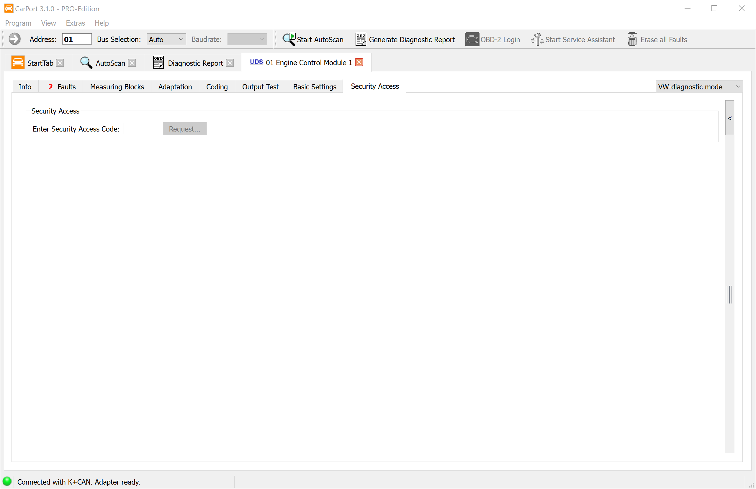
Security Access is a protection mechanism that unlocks certain diagnostic functions of a control unit only after entering a 5-digit numerical code. This prevents safety- or registration-relevant parameters from being changed accidentally or without authorization.
- Protocols: Exclusively in KWP2000 and UDS. In KWP1281, the Login / Coding II function is used instead.
Which functions are protected?
Security Access is typically required for the following actions:
- Adaptations (e.g., injector quantity values, key learning)
- Basic Settings (e.g., brake calibration)
- Coding changes in certain control units
Multiple access levels:
A control unit can have multiple access codes, each unlocking different functional areas. For example, one code may allow adaptation, while another code is required for Basic Settings.
💡 Tip: If description data is available for the control unit, CarPort displays the available access levels with plain text names in a selection list. An overview of frequently required codes can be found in the Appendix.
Step-by-step guide:
- Enter the 5-digit access code into the input field or select the appropriate entry from the list if description data is available.
- Click on
Request.... - Confirm the request in the displayed dialog.
- If successful, the corresponding function level is unlocked. CarPort displays this in the status indicator.
Behavior upon incorrect entry:
If an incorrect code is entered, the control unit blocks further access attempts for a manufacturer-defined waiting time (often 10–30 seconds, or longer for repeated incorrect entries). During this blocking time, the control unit rejects any further code – even the correct one.
⚠️ Warning: After an incorrect entry, wait for the full blocking time to elapse before starting a new attempt. An immediate re-entry – even with the correct code – can be rejected by the control unit and extend the blocking time.
Login / Coding II
The Login and Coding II functions are protection mechanisms of the older KWP1281 and KWP2000 diagnostic protocols. They fulfill a similar task to Security Access, but differ in how they work.
Difference from Security Access:
| Property | Security Access | Login / Coding II |
|---|---|---|
| Protocols | KWP2000, UDS | KWP1281, KWP2000 |
| Effect | Unlocks a function level | Executes an action directly or combines unlocking with coding |
| Code format | 5-digit numerical code | 5-digit numerical code |
Login:
The Login transmits a code to the control unit that directly unlocks or triggers a specific function. Unlike Security Access, which merely opens an authorization level, a Login can immediately cause a configuration change.
Coding II:
Coding II combines the entry of a code with a simultaneous coding change. This allows functions to be unlocked that are not accessible via regular Coding. A typical example is the activation of the cruise control system (CCS): By entering the appropriate code, the CCS function is activated in the control unit.
Step-by-step guide:
- Enter the code into the input field or select the appropriate entry from the list if description data is available.
- Click on
Login.... - Confirm the action in the displayed dialog.
ℹ️ Note: Whether a control unit supports Login or Coding II is specific to the control unit and depends on the firmware. Not every control unit offers this function. If description data is available, CarPort displays the available Login options with plain text designations.
SFD
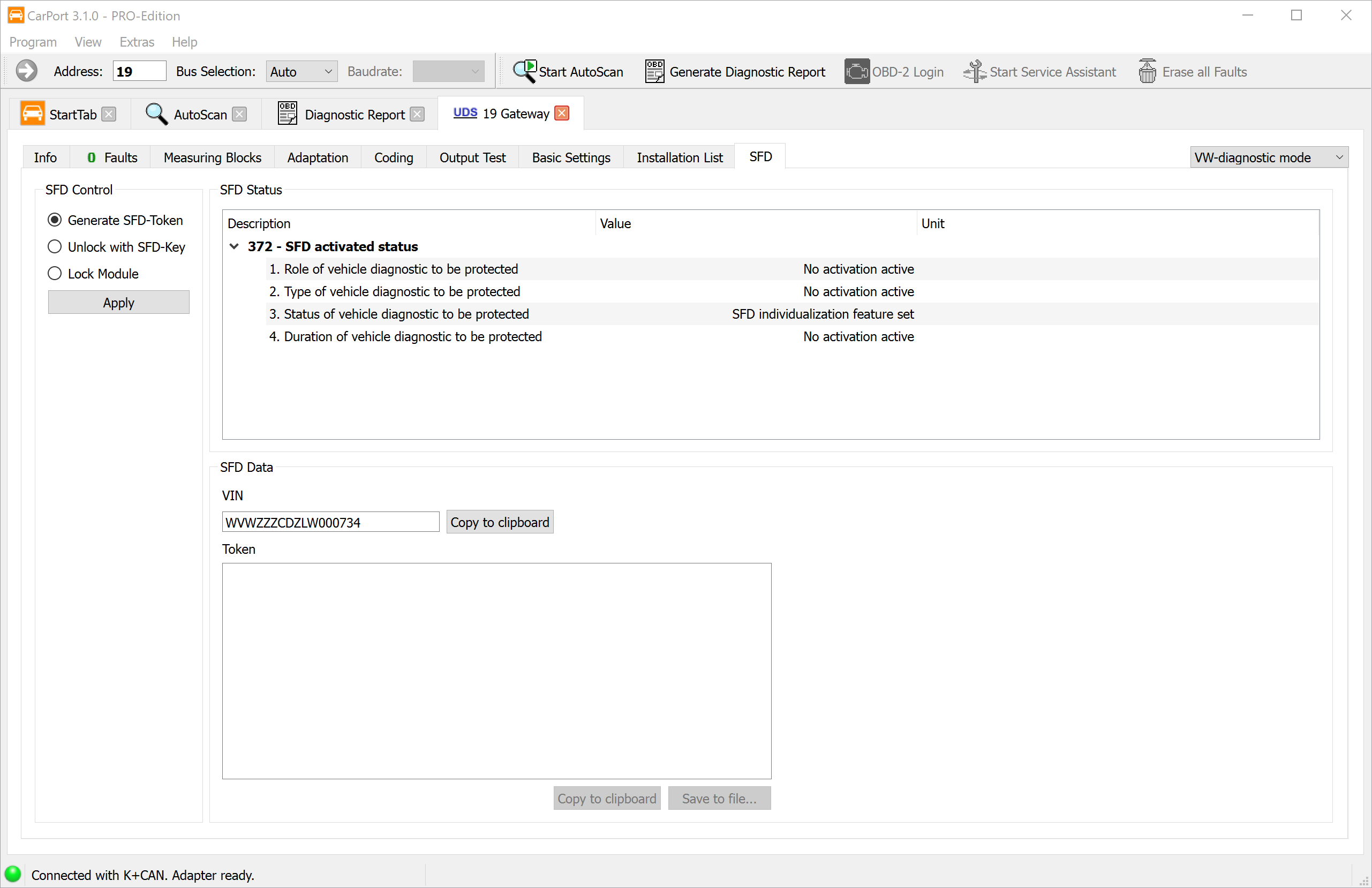
SFD (Vehicle Diagnostic Protection) is a cryptographic protection mechanism that the Volkswagen Group has been using in its control units since approx. model year 2020 (Golf 8, Octavia 4, Seat Leon 4, among others). In these vehicles, it replaces the previous Security Access and protects write diagnostic functions such as Coding, Adaptation, and Basic Settings from unauthorized access.
Difference from Security Access:
| Property | Security Access | SFD |
|---|---|---|
| Protection method | Static 5-digit numerical code | Cryptographic challenge-response method (Token + Key) |
| Vehicle binding | Code applies to all vehicles with the same control unit | Key is bound to the individual Vehicle Identification Number (VIN) |
| Protocols | KWP2000, UDS | Only UDS |
| Validity period | Permanently valid | Limited by time or per session (manufacturer-dependent) |
How do you recognize an SFD-protected control unit?
If a control unit is protected by SFD, CarPort displays the SFD tab after establishing the connection. The Security Access tab is not present in this case. Without prior SFD unlocking, write functions (Coding, Adaptation, Basic Settings) are blocked – read functions such as reading the fault memory and measuring values remain fully available.
Unlocking via the offline method:
CarPort supports SFD unlocking via an offline method. First, a vehicle-specific token is generated, which is then exchanged for an unlock code (key) at an external service (third-party provider).
ℹ️ Important: CarPort cannot generate SFD keys itself. The key calculation is done exclusively via external online services (third-party providers). However, CarPort supports the entire process of token generation and key application to make unlocking as simple as possible.
Step-by-step guide:
- Open the SFD tab in the connected control unit. The
SFD Statusarea shows the current protection state. - Under
SFD Control, select the optionGenerate SFD-Tokenand click onApply. - The control unit generates an individual token, which is displayed in CarPort. In addition, the Vehicle Identification Number (VIN) is displayed.
- Copy both values (token and VIN). Using the
Save to file...button, you can conveniently save both values in a text file. - Open the online service of an SFD provider (third-party provider) and enter the token and the VIN there to receive the unlock code (key).
- Switch back to CarPort. Under
SFD Control, select the optionUnlock with SFD-Key, enter the received key, and click onApply. - Upon successful unlocking, CarPort displays a confirmation. The write diagnostic functions are now available.
ℹ️ Note: SFD unlocking may be time-limited depending on the control unit. After expiration or after disconnecting, the process may need to be performed again.
Special Functions
Service Assistant
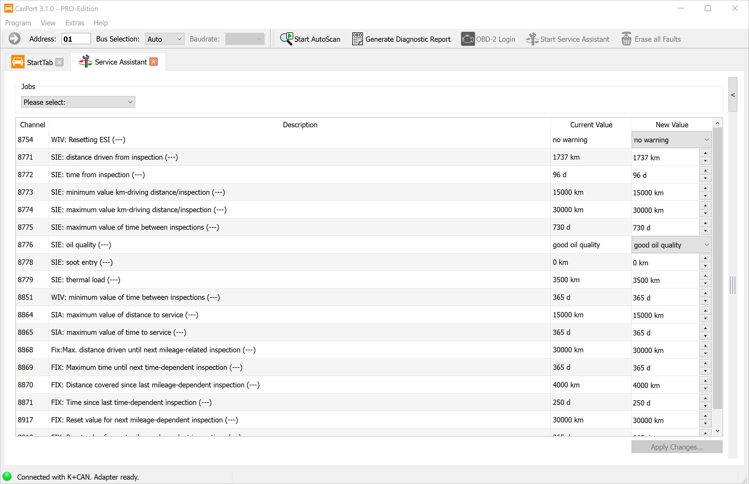
Vehicles of the Volkswagen Group feature a service interval display that reminds the driver of due maintenance work (e.g., oil change, inspection). This interval data is stored in the instrument cluster (speedometer) as adaptation channels and typically includes the remaining distance (in km) and the remaining time (in days) until the next service.
After performing maintenance, these counters must be manually reset so that the service interval display works correctly. Technically, this is done via the Adaptation function of the instrument cluster – the corresponding channels must be individually set to the appropriate values.
The Service Assistant in CarPort simplifies this process significantly: It summarizes all relevant service interval parameters in a clear view and allows resetting with just a few clicks – you do not need to know the individual adaptation channels and their target values.
Features:
- Clear presentation: All adaptation channels relevant to the service interval are displayed with their current and new values.
- Predefined jobs: In the
Jobssection, common service scenarios are available as predefined selection groups (e.g., reset oil change interval only, reset oil change + inspection). Selecting a job automatically marks the associated adaptation channels with the correct target values. - Change preview: All channels whose values will be changed by the selected job are highlighted in yellow – this way you can see exactly which parameters will be adapted before applying them.
Step-by-step instructions:
- Start the Service Assistant via the
Extras→Start Service Assistantmenu or via the button of the same name in the toolbar. - Select the desired service job in the
Jobssection (e.g., oil change, inspection, or both). - Check the changes highlighted in yellow in the overview. If necessary, you can adjust individual values manually.
- Click on
Apply Changes...to transfer the changes to the control module. - Turn the ignition off and on again so that the instrument cluster adopts the new values and the service interval display is updated.
💡 Tip: If the Service Assistant does not offer predefined jobs for your vehicle, you can also reset the service intervals manually via the Adaptation function of the instrument cluster.
Clear All Fault Codes
This function allows you to clear the fault memory of all control modules in the vehicle with a single command, without having to open each control module individually and clear the fault memory manually. This is particularly useful after extensive repair work where fault codes have occurred in multiple systems simultaneously.
Prerequisite:
Before the function is available, an AutoScan must be fully completed. This ensures that you know the current fault status of all control modules and consciously decide to clear the fault memories.
⚠️ Attention: By clearing, all stored fault codes and associated freeze frame data in all control modules will be lost. If necessary, export a Diagnostic Report beforehand to document the faults.
Clearing methods depending on vehicle type:
CarPort uses different clearing methods depending on the physical interface:
- CAN bus: CarPort uses a broadcast command that is received and evaluated by all control modules simultaneously. As a result, all fault memories are cleared almost at the same time – the process takes only a few seconds, regardless of the number of control modules.
- K-Line: Since a broadcast is not possible on the K-Line, CarPort sends the clear command sequentially to each individual control module that showed fault codes in the AutoScan. This process can take a few minutes depending on the number of affected control modules.
ℹ️ Note: Occasionally, control modules react differently to the CAN broadcast clear command than to a directly addressed clear command. If fault codes still remain in individual control modules after the global clearing, open the respective control module and clear the fault memory there manually.
Step-by-step instructions:
- Perform a complete AutoScan to record all control modules and their fault codes.
- Click on
Erase all Faults...in the toolbar or select the option via theExtras→Erase all Faults...menu. - Confirm the clear request in the displayed dialog.
- CarPort performs the clearing process and displays the progress.
- After completion, you should perform another AutoScan to verify that all fault memories have been successfully cleared.
Diagnostic Mode (UDS)
For control modules with the UDS protocol, diagnostic communication operates in different diagnostic sessions. Each session defines which commands the control module accepts and which functions are enabled. CarPort automatically switches to the appropriate mode when establishing a connection – however, in certain situations it may be necessary to switch the mode manually.
Switching the diagnostic mode:
With an open UDS connection, you will find a drop-down selection for the diagnostic mode in the top right of the control module window. The following modes are available:
| Mode | Description |
|---|---|
VW-diagnostic mode |
The standard mode for VAG-specific diagnostics. It is automatically set by CarPort after every connection establishment. All usual diagnostic functions are available here (fault memory, measuring values, coding, adaptation, basic setting, etc.). |
OBD-diagnostic mode |
Restricted diagnostic mode used for both generic OBD-2 diagnostics and VAG-specific diagnostics. Read functions (fault memory, measuring values, control module info) are available, but write accesses (coding, adaptation, basic setting, output test) are not possible. |
Programming mode |
Programming mode for flashing control module software. Required for firmware updates. |
End of line mode (EOL) |
Special mode for end-of-line tests at the end of the production line. Allows access to factory configuration functions. |
Development mode |
Development mode with extended diagnostic functions, normally used only in vehicle development. |
When does the mode need to be changed manually?
As a rule, manual switching is not necessary, as CarPort
automatically sets the VW-diagnostic mode. However, certain
special functions – especially individual coding options – require
switching to the End of line mode (EOL) or
Development mode.
ℹ️
Note: For vehicles with a Secure Gateway (SFD/UNECE), only the
OBD-diagnostic mode is available. The gateway blocks
switching to other diagnostic sessions as long as no gateway
authentication has taken place.
Debug Logs
If problems occur during diagnostics – e.g., communication errors, connection drops, or unexpected error messages – CarPort can record the entire communication with the vehicle as a debug log. These logs contain detailed information about all sent and received messages, the internal processing steps, as well as any errors or exceptions.
Debug logs are the most important tool for our development team to analyze the cause of a problem. When making a support request, you will therefore usually be asked to create a debug log and send it to us.
ℹ️ Note: Debug logs contain exclusively technical communication data between CarPort and the vehicle. No personal data is recorded.
Step-by-step instructions:
- Enable debug log recording via the
Extras→Write Debug Logsmenu. - A dialog opens showing the save location. The default path is the debug folder defined in the Program Settings.
- Perform the diagnostics normally until the problem occurs (e.g., communication error, unexpected error message).
- Exit CarPort.
- A Windows Explorer window automatically opens with the folder where the debug logs were saved. The log files have a timestamp in the file name, so you can easily identify the relevant file.
- Send the log file by email to our support team so that our development team can analyze the cause.
Program Settings
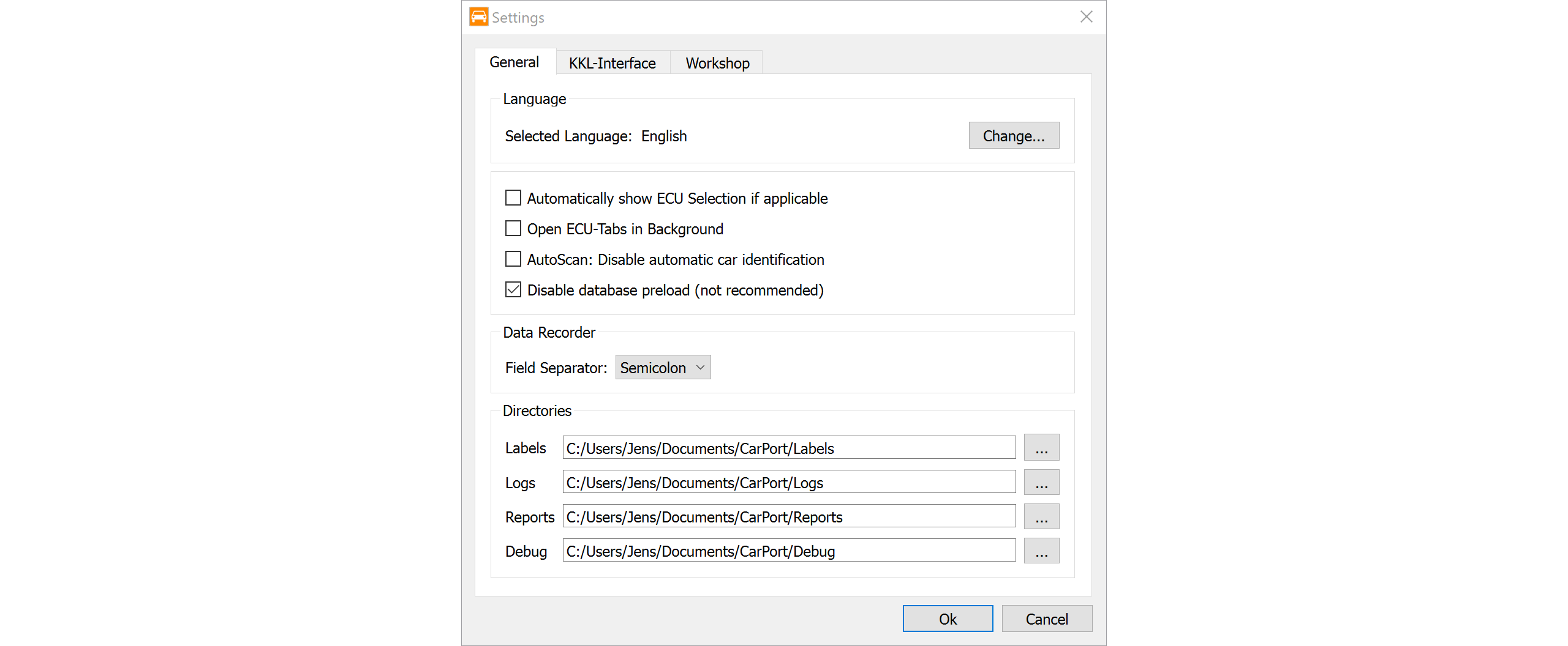
You can access the global configuration via the Program
→ Settings... menu. The settings are divided into different
tabs:
General:
Here you will find the basic program settings:
Language: Sets the display language of the user interface (restart required).
Automatic ECU selection:
Automatically show ECU Selection if applicable
For vehicles with a CAN bus (and gateway), the ECU selection opens automatically as soon as the interface is detected.Tabs in background:
Open ECU-Tabs in Background
ECU tabs are opened in the background so that you are not taken out of your current view.Manual vehicle selection in AutoScan:
AutoScan: Disable automatic car identification
Disables automatic vehicle identification. This forces the AutoScan dialog to always ask for manual selection (e.g., a scan list). Useful for special diagnostic scenarios.Database optimization:
Disable database preload (not recommended)
Disables loading the database at startup. Caution: Although this speeds up the program startup, it can lead to delays and timeouts during diagnostics.CSV export format:
Field Separator:
Configures the separator for log files (e.g., for measured values). By default, a comma,is used; in regions with a decimal comma (like Germany), a semicolon;is automatically used to ensure Excel compatibility.Directories: Here you define the storage locations for various files:
Labels: Storage location for description files.Logs: Destination folder for recorded measured values (CSV).Reports: Destination folder for diagnostic reports (PDF).Debug: Storage location for technical debug logs.
KKL-Interface:
Specific settings for communication via the K-line (older vehicles):
COM-Port:Manual selection of the COM port if automatic detection fails.Bus idle time:A waiting time in seconds that the interface waits before transmitting. Useful for unstable connections (default values are usually sufficient).Fast Init:Activates an accelerated connection protocol for KWP2000. Disable this option if connection problems occur.
Workshop:
- Workshop information: Here you can enter your company data (equipment number, importer number, workshop code). This data is transmitted to the ECU during write accesses (e.g., coding) and saved there. Note: Leave the fields empty to retain the information that is already saved in the ECU.
Appendix
List of Known Security Access Codes
01 – Engine Control Unit (ECU)
| Code | Function | Notes |
|---|---|---|
| 12233 | Access to adaptation channels | Standard for 4-cylinder TDI engines (1Z, AHU, AFN, ALH, ASV, AXR, ASZ, etc.) |
| 27971 | DPF functions | For particulate filter adaptations |
| 17575 | DPF regeneration | Forced regeneration of diesel particulate filter |
| 79153 | Special functions | Not available for all control units |
| 26262 | Alternative adaptation | For some V6 TDI and other ECU variants |
| 22158 | Engine code AEL | For 2.5l TDI engines |
Typical applications:
- Adjust idle speed
- Modify EGR (Exhaust Gas Recirculation) values
- Adjust injection quantity
- DPF service and forced regeneration
03 – Brake Electronics (ABS/ESP)
| Code | Function | Notes |
|---|---|---|
| 20103 | General enable | Basic code for various functions |
| 40168 | Basic setting | Calibrate steering angle sensor, ESP system |
| 11966 | Hydraulic brake assist | |
| 25757 | Brake stabilization | |
| 25004 | Brake booster | Adaptation |
| 31857 | Basic setting & adaptation | Extended enable |
| 24990 | Adaptation enable | General |
| 40304 / 44595 | Brake disc drying |
Typical applications:
- Calibrate/adjust steering angle sensor (G85)
- Recode ESP system after repair
- Adjust XDS (electronic differential lock)
- Set up ABS control unit after replacement
09 – Central Electronics
| Code | Function | Notes |
|---|---|---|
| 12151 | Adaptation enable | e.g., Audi A6 4F |
| 31347 | Security access | Standard for many vehicles |
Typical applications:
- Coming-Home/Leaving-Home functions
- Door locking at speed
- Power window functions
- Lighting adaptations
17 – Instrument Cluster
| Code | Function | Notes |
|---|---|---|
| 20103 | Adaptation enable | Vehicles before model year 2016 |
| 25327 | Variant | From model year 2016 |
| 47115 | Adaptation enable | From model year 2016 |
| 13861 | Instrument cluster | Standard login for adaptations |
Typical applications:
- Reset service interval
- Configure display options
- Immobilizer-related settings
34 – Level Control / Air Suspension
| Code | Function | Notes |
|---|---|---|
| 20103 | Basic enable | General access |
| 31564 | Calibration | Height adjustment, learn control position |
Typical applications:
- Calibrate vehicle height (lowering/raising)
- Relearn control position after repair
- Adjust level sensors
- Air suspension basic setting
44 – Steering Assistance
| Code | Function | Notes |
|---|---|---|
| 19249 | Adaptation enable | Standard |
| 28183 | Driving profile selection | Adaptation IDE06419 |
| 44595 | Extended functions | Special applications |
46 – Comfort System (Central Locking)
| Code | Function | Notes |
|---|---|---|
| 22790 | Adaptation | Comfort functions |
Typical applications:
- Automatic locking at speed
- Horn beep on lock/unlock
- Single door or all door unlocking
- Window closing via remote control
55 – Headlight Range Control
| Code | Function | Notes |
|---|---|---|
| 15284 | Adaptation enable | Standard |
| 20103 | Alternative | General access |
5F – Infotainment
| Code | Function | Notes |
|---|---|---|
| 20103 | Adaptation | Infotainment settings |
6C – Rear View Camera
| Code | Function | Notes |
|---|---|---|
| 22351 | Calibration | Adaptation enable for rear view camera |
Other Control Units
| Address | System | Codes |
|---|---|---|
| 05 | Access/Start Authorization | 20103 |
| 08 | Climate/Heater Electronics | 20103 |
| 10 | Parking Aid | 20103, 71679 |
| 13 | Distance Control (ACC) | 14117 |
| 14 | Wheel Damping | 20103 |
| 18 | Auxiliary Heater | 20103 |
| 19 | Diagnostic Interface | 20103 |
| 26 | Roof Electronics | 06777 |
| 2B | Steering Column Lock | 20103 |
| 3C | Lane Change Assist | 20103 |
| 42 | Driver Door Electronics | 20103 |
| 4B | Multifunction Control Module | 20103 |
| 52 | Passenger Door Electronics | 20103 |
| 53 | Electronic Parking Brake | 21673 (Touareg 7P) |
| 65 | Tire Pressure Monitoring | 20103 |
| 75 | Telematics | 20103 |
| A5 | Front/Forward Camera | 20103 |